HI28B2039 FerriShield, HI28B2039 Datasheet - Page 7
HI28B2039
Manufacturer Part Number
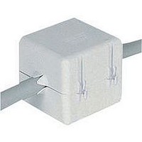
HI28B2039
Description
FERRITE BEAD
Manufacturer
FerriShield
Datasheet
1.HI28B2039.pdf
(40 pages)
Specifications of HI28B2039
Impedance
410ohm
Width (latch Included)
45.7mm
Internal Diameter
11mm
Frequency
100MHz
Size
43.2 Mm X 50.8 Mm X 45.7 Mm
Lead Free Status / RoHS Status
Lead free / RoHS Compliant


employed with ferrite, it is best to prepare a properly engineered
calculation of expected results. An empirical trial and error
method may leave the circuit close to borderline performance
without adequate safety margins. As indicated previously, a
wide range of formulations is possible. The major application
factors to be used when defining a specific ferrite solution for a
particular interference problem include the following:
to the performance of a given ferrite composition (figure 1
on previous page). The optimum profile would be a ferrite
in which the highest attenuation level coincides with the
disruptive frequency (A). That same ferrite could be used even
if the frequency falls in a lower area of its impedance curve
(B) but there would be correspondingly reduced attenuation.
Conversely, a different ferrite formulation could be employed
in the same frequency situation with the intent of using a
lower part of its performance curve (C). Space and weight
considerations are not normally a concern since good quality
ferrites provide high performance per a given cubic volume.
characteristics of the source and load coupled with the ferrite
suppressor is developed as follows:
Organizing the Engineering Model
impedance is 250 ohms, then the insertion loss will be:
To understand the various practical modeling techniques
- Frequency where maximum attenuation is required.
- Amount of attenuation needed.
- Ferrite permeability formulation characteristics as they
- Ferrite formulation consistency (i.e., expected range of
- Installation environment and mechanical attachment
The frequency range requiring attenuation must be matched
The
If the circuit impedance (Z
20 Log
relate to the frequency range in question (i.e., initial
permeability)
variation in attenuation performance)
requirements.
Insertion
Loss (dB)
Where:
Insertion Loss = A measure of the effectiveness of
a filter, expressed in decibels, is described as the
ratio of voltages with, and without, the filter in
the circuit.
modeling
Z
Z
Z
10
A
B
F
(50+250)/50 = 15.56 dB
= Source Impedance
= Ferrite Impedance
= Load Impedance
=
procedure
20 log
A
10
+ Z
(Z
B
to
A
) is 50 ohms and the ferrite
(Z
+ Z
A
calculate
+ Z
B
+ Z
B
)
F
)
impedance
7
provided by a ferrite suppressor can differ somewhat as the
original circuit impedance varies. The ferrite is more effective
when the circuit impedance is low. For example, by using the
same 250 ohm ferrite in a 75 ohm circuit, the result will be:
the number of turns or passes through the ferrite (figures 3
and 4), or to use a larger amount of ferrite (cubic volume) in the
circuit in order to achieve the same level of insertion loss (fig. 2).
By increasing the number of turns (passes) through the ferrite
opening, the “effective magnetic path” is increased _ impedance
then increases by the square of the number of turns (N
two turns (2
volume is added, impedance increases on almost a direct
percentage basis; i.e., a 100 percent increase in volume will
provide about 100 percent increase in impedance (figure 2)
in most situations according to certain prescribed dimensional
ratios.
reverse by solving for a desired insertion loss goal. The result
yields an impedance requirement. This can be matched to
known performance profiles of existing ferrite configurations in
the geometric style best suited for mechanical and packaging
requirements.
As an example, a 15dB insertion loss is required for a flat ribbon
cable at 100 MHz. Using the formula:
ribbon cable style part that closely matches is #28B2480 with a
250½ impedance at 100 MHz.
should be confirmed by testing. Although these ferrites are
“linear,” the term is relative to the common operating range of
temperatures. The permeability is different at every degree of
temperature. The published initial permeability (µ i ) nomenclature
applies to standard temperature, 59°F (15°C) only. There are
only minor impedance differences, however, throughout normal
operational ranges and up to 180° F (82°C).
Properties on page 33.
Even though the same unit of ferrite is used, the attenuation
With a high circuit impedance, it may be possible to increase
An alternative modeling procedure may also be structured in
Next, refer to the Attenuation Properties on page 36. The flat
Once the ferrite suppressor is installed in the circuit, results
a powerful insertion loss device
20 Log
Insertion Loss (dB) = 20 log
Where: IL = 15 dB
2
) = 4 times the impedance. When additional ferrite
10
Z
Z
Z
15dB = 20 Log
0.75 = Log
5.625 = 50 + Z
Z
A
B
F
F
(75 + 250)/75 = 12.7 dB
= 25 ohms
= 231.25 ohms
= 25 ohms
= Unknown ferrite impedance
(solve for this value)
10
50
(
10
50 + Z
F
(
50
25 + 25
50 + Z
10
F
)
F
(Z
)
A
(Z
+ Z
A
+ Z
B
+ Z
See Material
B
)
F
)
2
) ; i.e.,
Related parts for HI28B2039
Image
Part Number
Description
Manufacturer
Datasheet
Request
R

Part Number:
Description:
EMI Connector Gaskets D Shape RFI Shielding Gasket
Manufacturer:
FerriShield
Datasheet:
Part Number:
Description:
EMI Connector Gaskets Shielding Contacts .138 Square
Manufacturer:
FerriShield
Datasheet:
Part Number:
Description:
EMI Connector Gaskets Micro D Shape RFI Shielding Gasket
Manufacturer:
FerriShield
Datasheet:
Part Number:
Description:
EMI Connector Gaskets Rectangular RFI Shielding Gasket
Manufacturer:
FerriShield
Datasheet:
Part Number:
Description:
EMI Connector Gaskets D Shape RFI Shielding Gasket
Manufacturer:
FerriShield
Datasheet:

Part Number:
Description:
EMI Connector Gaskets 25 Pin D-Sub Shield
Manufacturer:
FerriShield
Datasheet:
Part Number:
Description:
EMI Connector Gaskets 37 Pin D-Sub Shield
Manufacturer:
FerriShield
Datasheet:
Part Number:
Description:
EMI Connector Gaskets Rectangular RFI Gasket 24
Manufacturer:
FerriShield
Datasheet:
Part Number:
Description:
EMI Connector Gaskets 9 Pin D-Sub Shield
Manufacturer:
FerriShield
Datasheet:

Part Number:
Description:
EMI Connector Gaskets Rectangular RFI Shielding Gasket
Manufacturer:
FerriShield
Datasheet:
Part Number:
Description:
EMI Connector Gaskets 50 Pin D-Sub Shield
Manufacturer:
FerriShield
Datasheet:
Part Number:
Description:
EMI Connector Gaskets D Shape RFI Shielding Gasket
Manufacturer:
FerriShield
Datasheet:
Part Number:
Description:
EMI Connector Gaskets 15 Pin D-Sub Shield
Manufacturer:
FerriShield
Datasheet:
Part Number:
Description:
EMI Gaskets & Grounding Pads Polyester with Cu-Ni 500KHz-1GHz
Manufacturer:
FerriShield
Datasheet:

Part Number:
Description:
EMI Gaskets & Grounding Pads Hot Melt Adhesive 100MHz-1GHZ
Manufacturer:
FerriShield
Datasheet: