HI28B2039 FerriShield, HI28B2039 Datasheet - Page 14
HI28B2039
Manufacturer Part Number
HI28B2039
Description
FERRITE BEAD
Manufacturer
FerriShield
Datasheet
1.HI28B2039.pdf
(40 pages)
Specifications of HI28B2039
Impedance
410ohm
Width (latch Included)
45.7mm
Internal Diameter
11mm
Frequency
100MHz
Size
43.2 Mm X 50.8 Mm X 45.7 Mm
Lead Free Status / RoHS Status
Lead free / RoHS Compliant


For attenuation properties by frequency, see page 32
28 material
telecom cable snaps
Available in standard colors gray (i.e., SS28B2034) and black (i.e., SS28B2034K)
Patent Nos. 5,003,278 and 5,764,125
very high impedance multi-turn sleeve snap
Available in standard colors gray (i.e., SS28B2035) and black (i.e., SS28B2035K)
Patent No. 5,003,278
cable bundle clamp
pre-molded sleeve
special purpose shielding bar
PART No.
PART No.
PART No.
PART No.
PM28B3375
PM28B0625
PM28B1625
PM28B0686
PM28B0736
PART No.
SS28B2035
SS28B2035-2 AS28B2035-2
SS28B2035-3 AS28B2035-3
BC28B1251
BC28B1501
BC28B1500
SB28B5630
WITH SERPENTINE CABLE THREADING CAPABILITY.
By increasing the number of times the circuit passes through the ferrite
core, the effective magnetic path is lengthened yielding a significant
increase in impedance. See page 6, figures 3 and 4. The gain is equal to
N 2 , the square of the number of turns, and depending on the circuit cable
load and frequencies involved, much of the increase can be realized.
Cables may be “looped back through” as shown at left; or, “looped over
the top” as shown at left (insert).
In an alternate configuration, separate cable circuits can be accommodated
without saturation. Three styles permit different approaches:
Each is available with an optional adhesive foam pad mounting base.
WITH UNIVERSAL MOUNTING STRAP.
up to 1.00” (25,4mm). Allows single location for RFI suppression for
multiple cables and wiring runs. Each circuit reacts independently with
the suppression material without saturation. Adhesive mount base also
provides a centered .203” (5,1mm) diameter hole for optional hardware
attachment. Quick-release closure clip allows easy addition or removal of
wires.
WITH INTERNAL FRICTION GRIP
ferrite suppressor. Assembles to cable prior to termination by threading
in one end and out the other. Neutral gray standard color. Five sizes
accommodate cable diameters from .200” to .430” (5,1 to 10,9mm).
The preferred alternative to cable over-molding, shrink tubing, taping, tie
wraps and other costly secondary installation operations. A drop of water
in the I.D. during assembly will facilitate sliding into position.
For situations where extremely high amounts of attenuation are needed and/or
multiple passes through a traditional ferrite I.D. are not practical or sufficient.
Simply wrap cable in a spiral around bar for optimum absorption.
WITH END PORTS FOR FLAT-OVAL CABLES.
assembly in fully enclosed nylon case. Two sizes: one for 4-conductor
and one for 6-conductor standard telecom flat-oval cable. Clamps around
cable with appropriate pressure to maintain desired position.
SS28B2034
SS28B2031
• One individual size fits most applications
• For round or flat cables wound axially or attached longitudinally
• Attachment with cable ties or optional adhesive pad
• Sandwiching cable between two bars provides up to three times the
The 1-hole allows two passes of a cable with a diameter up to .365”
(9 ,3mm) or three passes of a cable with a diameter up to .243” (6,2mm).
The 2-hole allows two passes of a cable with a diameter up to .335” (8,5mm).
The 3-hole allows three passes of cable with a diameter up to .203”
impedance of a single bar depending on frequency
Cable Size
w/Adhesive
AS28B2035
w/ adhesive
BA28B1251
BA28B1501
BA28B1500
w/ adhesive
SB28B5630A
4 conductor
6 conductor
.192
.310
.310
.375
.430
10,9
A
wideband ferrites- up to 1GHz applications
4,8
7,9
7,9
9,5
.290
.400
.400
.465
.520
Description
.585
.700
1.38
1.63
1.63
1-hole
2-hole
3-hole
A
B
13,2
10,2
10,2
11,8
.365
7,4
A
14,9
17,8
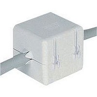
Exterior PVC sheath pre-molded over
14
35,1
41,4
41,4
A
.465
.715
.715
.776
.776
9,3
1.155
1.155
1.155
1.250
1.255
A
C
B
For cable bundle diameters
11,8
18,2
18,2
19,7
19,7
29,3
29,3
29,3
31,8
31,9
1.00
.75
.75
1.250
1.250
1.250
B
2.01
1.82
2.38
2.38
2.38
5.630
19,1
19,1
25,4
.585
.675
Box-shaped ferrite
B
C
D
51,1
46,2
60,5
60,5
60,5
31,8
31,8
31,8
B
14,9
17,1
143,0
.250
.250
.250
.250
.250
1.125
1.125
1.125
(5,8mm).
1.000
1.000
.250
.230
.875
C
D
E
6,4
6,4
6,4
6,4
6,4
28,6
28,6
28,6
C
6,4
5,8
22,2
25,4
25,4
1.335
1.335
1.335
.780
.335
.203
1.00
.960
.772
D
.120
.187
SS28B2035-2
SS28B2035
SS28B2035-3
19,8
SS28B2034 - 4-conductor
SS28B2031 - 6 conductor
C
1-hole
E
2-holes
F
3-holes
8,5
5,2
Adhesive pad
24,4
19,6
33,9
33,9
33,9
D
25,4
E
1.71
1.96
1.96
3,0
4,7
1.230
1.230
1.230
A
* Optional Adhesive pad .030 (0,76)
D
Optional Adhesive Pad .030 (0,76)
Optional Adhesive Pad .030 (0,76)
Optional Adhesive Pad .030 (0,76)
Optional Adhesive Pad .030 (0,76)
.800
.800
.800
.800
.800
E
F
41,7
48,0
48,0
*
.680
.768
C
A
B
31,2
31,2
31,2
D
F
G
20,3
20,3
20,3
20,3
20,3
B
B
one pass: 500 @ 100MHz
B
B
B
B
17,3
19,5
IMPEDANCE IN OHMS ref.
1N=129* 2N=2
1N=270* 3N=3
1N=340*
G
A
A
IMPEDANCE IN OHMS
A
A
IMPEDANCE IN OHMS
B
A E
A E
* @ 100 MHz
IMPEDANCE IN OHMS
IMPEDANCE IN OHMS
Patent No. 5,200,730
138 @ 100MHz
177 @ 100MHz
133 @ 100MHz
140 @ 100MHz
120 @ 100MHz
225 @ 100MHz
196 @ 100MHz
176 @ 100MHz
B
220 @ 100MHz
200 @ 100MHz
depending on circuit
load and frequency
REF
C
2
2
F
F
=9NΩ
A
=4NΩ
C
C
C
C
C
E
F
C
E
C
E
E
ref.
ref.
D
D
D
D
D
D
Related parts for HI28B2039
Image
Part Number
Description
Manufacturer
Datasheet
Request
R

Part Number:
Description:
EMI Connector Gaskets D Shape RFI Shielding Gasket
Manufacturer:
FerriShield
Datasheet:
Part Number:
Description:
EMI Connector Gaskets Shielding Contacts .138 Square
Manufacturer:
FerriShield
Datasheet:
Part Number:
Description:
EMI Connector Gaskets Micro D Shape RFI Shielding Gasket
Manufacturer:
FerriShield
Datasheet:
Part Number:
Description:
EMI Connector Gaskets Rectangular RFI Shielding Gasket
Manufacturer:
FerriShield
Datasheet:
Part Number:
Description:
EMI Connector Gaskets D Shape RFI Shielding Gasket
Manufacturer:
FerriShield
Datasheet:

Part Number:
Description:
EMI Connector Gaskets 25 Pin D-Sub Shield
Manufacturer:
FerriShield
Datasheet:
Part Number:
Description:
EMI Connector Gaskets 37 Pin D-Sub Shield
Manufacturer:
FerriShield
Datasheet:
Part Number:
Description:
EMI Connector Gaskets Rectangular RFI Gasket 24
Manufacturer:
FerriShield
Datasheet:
Part Number:
Description:
EMI Connector Gaskets 9 Pin D-Sub Shield
Manufacturer:
FerriShield
Datasheet:

Part Number:
Description:
EMI Connector Gaskets Rectangular RFI Shielding Gasket
Manufacturer:
FerriShield
Datasheet:
Part Number:
Description:
EMI Connector Gaskets 50 Pin D-Sub Shield
Manufacturer:
FerriShield
Datasheet:
Part Number:
Description:
EMI Connector Gaskets D Shape RFI Shielding Gasket
Manufacturer:
FerriShield
Datasheet:
Part Number:
Description:
EMI Connector Gaskets 15 Pin D-Sub Shield
Manufacturer:
FerriShield
Datasheet:
Part Number:
Description:
EMI Gaskets & Grounding Pads Polyester with Cu-Ni 500KHz-1GHz
Manufacturer:
FerriShield
Datasheet:

Part Number:
Description:
EMI Gaskets & Grounding Pads Hot Melt Adhesive 100MHz-1GHZ
Manufacturer:
FerriShield
Datasheet: