HV843K7-G Supertex, HV843K7-G Datasheet - Page 5
HV843K7-G
Manufacturer Part Number
HV843K7-G
Description
Display Drivers Low Noise Dual
Manufacturer
Supertex
Datasheet
1.HV843K7-G.pdf
(6 pages)
Specifications of HV843K7-G
Driver Type
EL Lamp Drivers
Maximum Operating Temperature
+ 85 C
Mounting Style
SMD/SMT
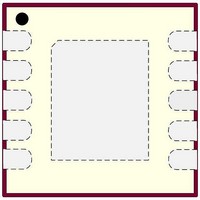
Package / Case
DFN-10
Maximum Output Current
4 mA
Minimum Operating Temperature
- 40 C
Lead Free Status / RoHS Status
Lead free / RoHS Compliant


Split Supply Configuration
The HV843 can be used in applications operating from a
battery where a regulated voltage is available. This is shown
in Fig. 2. The regulated voltage can be used to drive the
internal logic of HV843. The amount of current used to drive
Fig. 2 - Split Supply Configuration
Pin Configuration and Description
Pin #
10
1
2
3
4
5
6
7
8
9
RSW-Osc
Function
Regulated Voltage = V
COM
GND
VDD
EL2
EL1
Supertex inc.
CS
C1
C2
LX
Battery Voltage = V
V
0 = OFF
IH
= ON
Description
Enable input signal for EL Lamp 1. Logic high will turn ON the EL lamp 1 and logic low will turn it
OFF. Refer to the function table.
Input voltage supply pin.
External resistor connection to set both the switching MOSFET frequency and EL Lamp frequency.
The external resistor should be connected between VDD and this pin. The EL lamp frequency is the
switching frequency divided by 512. The switching frequency is inversely proportional to the resis-
tor value. A 845kΩ resistor will provide a nominal switching frequency of 102kHz and an EL lamp
frequency of 200Hz. To change the frequency to f
mined as R
Enable input signal for EL Lamp 2. Logic high will turn ON the EL lamp 2 and logic low will turn it
OFF. Refer to the function table.
Device ground.
Drain of internal switching MOSFET. Connection for an external inductor. When the switching
MOSFET is turned ON, the inductor is being charged. When the MOSFET is turned OFF, the energy
stored in the inductor is transferred to the high voltage capacitor connected at the CS pin.
Connect a 100V capacitor between this pin and GND. This capacitor stores the energy transferred
from the inductor.
Common lamp connection for both EL1 and EL2. Connect one end of both the lamps to this pin.
EL lamp 2 connection. For optimum performance, the smaller of the two lamps should be connected
to this pin.
EL lamp 1 connection. For optimum performance, the larger of the two lamps should be connected
to this pin.
V
0 = OFF
IH
= ON
DD
IN
SW-Osc1
●
1235 Bordeaux Drive, Sunnyvale, CA 94089
C
C
DD
IN
= (845 x 200) / f
R
SW-Osc
1
2
3
4
5
C1
VDD
RSW-Osc
C2
GND
EL1
HV843
kΩ.
5
the internal logic is less than 200µA. Therefore, the regu-
lated voltage could easily provide the current without being
loaded down.
COM
EL1
EL2
CS
LX
10
9
8
7
6
EL1
●
, the value of the resistor R
Tel: 408-222-8888
L
EL Lamp 1
X
D
EL Lamp 2
●
C
www.supertex.com
S
SW-Osc1
can be deter-
HV843
Related parts for HV843K7-G
Image
Part Number
Description
Manufacturer
Datasheet
Request
R

Part Number:
Description:
32-channel Serial To Parallel Converter With High Voltage Push-pull Outputs - Supertex, Inc
Manufacturer:
Supertex, Inc.
Datasheet:
