ZHX2022MV040THTR Zilog, ZHX2022MV040THTR Datasheet
ZHX2022MV040THTR
Specifications of ZHX2022MV040THTR
Available stocks


Related parts for ZHX2022MV040THTR


ZHX2022MV040THTR Summary of contents
Page 1
... ZHX2022 FIR Transceiver Product Specification PS021802-1005 ZiLOG Worldwide Headquarters • 532 Race Street • San Jose, CA 95126-3432 www.ZiLOG.com ...
Page 2
... ZiLOG Worldwide Headquarters 532 Race Street San Jose, CA 95126-3432 www.ZiLOG.com ZiLOG is a registered trademark of ZiLOG Inc. in the United States and in other countries. All other products and/or service names mentioned herein may be trademarks of the companies with which they are associated. Document Disclaimer © ...
Page 3
Table of Contents Description . . . . . . . . . . . . . . . . . . . . . . . . . . . . . . . . . . . . ...
Page 4
List of Figures Figure 1. FIR Transceiver Block Diagram . . . . . . . . . . . . . . . . . . . . . . . . . . . . . 3 Figure ...
Page 5
... Description Whether you need to mount the IrDA transceiver so that its communication is par- allel or perpendicular to the plane of the PCB, the ZiLOG ZHX2022 is the solution for applications in portable products, such as USB Adapters, notebook PCs, print- ers, mobile phones, digital cameras, handheld devices, or personal data assis- tants (PDAs). Designed to support all IrDA data rates Mbits/second as well as LocalTalk™ ...
Page 6
... Medical and industrial data collection Parts Table Part ZHX2022MV040THTR Oriented in carrier tape for side-view surface ZHX2022TV040THTR Oriented in carrier tape for top-view surface Note: All ZiLOG devices are available lead free. ZHX2022 has always been lead free. These devices meet or exceed RoHS Directive 2002/95/EC ...
Page 7
Block Diagram Figure 1 is the block diagram for the FIR transceiver. Mode SD Txd Figure 1. FIR Transceiver Block Diagram Pinout and Pin Description Figure 2. Pinout PS021802-1005 Amplifier Comparator Logic & Control V GND CC1 FIR Transceiver Tri-State ...
Page 8
Table 1. Pin Description Pin Number Function Description 1 V LEDA Connect LEDA directly to either V CC2 to V than 3 external resistor might be necessary for reducing the internal power dissipation. 2 LEC IRED cathode, internally ...
Page 9
Electrical and Timing Specifications Notes: Reference point: Ground Pin 8, unless otherwise noted Typical values are for design aid only, not guaranteed nor subject to production testing. Table 2. Absolute Maximum Ratings Parameter Supply voltage range, transceiver 0 V < ...
Page 10
Notes: Reference point pin: GND, unless otherwise noted Typical values are for design aid only, not guaranteed nor subject to production testing. Table 3. Eye Safety Information Parameter Virtual source size Maximum Intensity for Class 1 IEC60825 Due ...
Page 11
Table 4. Electrical Characteristics—Transceiver (Continued) Parameter Test Conditions Shutdown supply current SD=High, Mode=Floating E SD=High, Mode=Floating E SD=High, T=85 °C, Mode=Floating, not ambient light sensitive Operating temperature range Output voltage low Output voltage high ...
Page 12
Notes: T =25 °C, V amb Typical values are for design aid only, not guaranteed nor subject to production testing. Table 5. Optoelectronic Characteristics—Receiver Parameter Test Conditions 9.6 kbit/s to 115.2 kbit/s Minimum detection threshold λ=850 nm to 900 nm ...
Page 13
Table 5. Optoelectronic Characteristics—Receiver (Continued) Parameter Test Conditions input irradiance=100 mW/m 1.152 Mbit/s input irradiance=100 mW/m 576 kbit/s input irradiance=100 mW/m < 115.2 kbit/s Receiver start up time After completion of shutdown programming sequence Power on delay Latency Note: All ...
Page 14
Table 6. Optoelectronic Characteristics—Transmitter (Continued) Parameter Test Conditions α Output radiant intensity recommended application Txd=High, SD=Low, circuit VCC1=VCC2=3.3 V Internally current-controlled, no external resistor Output radiant intensity VCC1=5.0 V, a=0 °, 15 ° Txd=Low or SD=High, (Receiver is inactive as ...
Page 15
... Recommended Circuit Diagram ZiLOG transceivers integrate a sensitive receiver and a built-in power driver. The combination of both needs a careful circuit board layout. The use of thin, long, resistive, and inductive wiring should be avoided. The inputs (Txd, SD, Mode) and the output Rxd should be directly (DC) coupled to the I/O circuit. See Figure 3 and Table 7 ...
Page 16
LEDA may be powered from a separate unregulated voltage supply.) Vcc= 2.7 to 3.3 V IrDA enabled I/O Controller, Microcontroller, ENDEC, or Vcc= 3.4 to 5.5 V I/O Controller, Microcontroller, Note: Lands to Pins ...
Page 17
... In the description, already different I/Os are mentioned. Different combinations are tested and the function verified with the special drivers available from the I/O sup- pliers. In special cases, refer to the I/O manual, the ZiLOG application notes, or contact directly ZiLOG Sales, Marketing or Application. ...
Page 18
Figure 4. Mode Switching Timing Diagram Table 8. Truth Table Inputs SD Txd Optical Input Irradiance mW/m high x low high µ low high > low low low low > Min. Detection Threshold Irradiance < Max. Detection Threshold ...
Page 19
After waiting t is limited by the maximum allowed pulse length. After that, Txd is enabled as normal Txd input, and the transceiver is set for the high bandwidth (576 kbit Mbit/s) mode. Setting to the Lower ...
Page 20
... ZHX2022 Soldering and Cleaning Recommendations Follow these recommendations to maintain the performance of the ZHX2022 transceivers. Reflow Soldering Note: Please refer to ZiLOG’s Lead-Free Solder Reflow: Packaging Application Note (AN0161, http://www.zilog.com/docstools.asp) for more information about the solder profile. Manual Soldering • Use 63/37 or silver solder. ...
Page 21
Current Derating Diagram Figure 6 shows the maximum operating temperature when the device is operated without external current limiting resistor. A power dissipating resistor of 2 ommended from the cathode of the IRED to Ground for supply voltages above 4 ...
Page 22
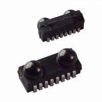
Mechanical Specifications Figure 7. Package Dimensions in mm PS021802-1005 2022 FIR Transceiver 18 ...
Page 23
Taping Specifications Figure 8. Reel Dimensions in mm Version Tape Width mm C PS021802-1005 A max 330 60 FIR Transceiver min. W max. W min 24.4 30.4 ...
Page 24
Figure 9. Tape Dimensions in mm PS021802-1005 FIR Transceiver 20 18269 ...
Page 25
Figure 10. Tape Dimensions in mm PS021802-1005 FIR Transceiver 2022 18283 21 ...
Page 26
... Customer Feedback Form If you experience any problems while operating this product you note any inaccura- cies while reading this product specification, please copy and complete this form, then mail it to ZiLOG (see Return Information, below). We also welcome your suggestions! Customer Information Name ...