ZHX2022MV040THTR Zilog, ZHX2022MV040THTR Datasheet - Page 13
ZHX2022MV040THTR
Manufacturer Part Number
ZHX2022MV040THTR
Description
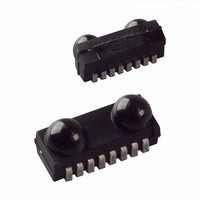
Fiber Optic Transmitters, Receivers, Transceivers FIR IrDA 4 MBITS
Manufacturer
Zilog
Datasheet
1.ZHX2022TV040THTR.pdf
(26 pages)
Specifications of ZHX2022MV040THTR
Product
Transceiver
Data Rate
115.2 Kbps
Wavelength
900 nm
Maximum Rise Time
40 ns
Maximum Fall Time
40 ns
Pulse Width Distortion
1.8 us
Operating Supply Voltage
2.7 V to 5.5 V
Maximum Operating Temperature
+ 85 C
Minimum Operating Temperature
- 25 C
Package / Case
UltraSlim
Idle Current, Typ @ 25° C
2mA
Link Range, Low Power
-
Operating Temperature
-25°C ~ 85°C
Orientation
Top View
Shutdown
*
Size
9.7mm x 4.7mm x 4mm
Standards
IrPHY 1.4
Supply Voltage
2.7 V ~ 5.5 V
Lead Free Status
Contains lead
Lead Free Status / RoHS Status
Lead free / RoHS Compliant
Lead Free Status / RoHS Status
Lead free / RoHS Compliant
Available stocks
Company
Part Number
Manufacturer
Quantity
Price
Company:

Part Number:
ZHX2022MV040THTR
Manufacturer:
FUJIKURA
Quantity:
8 000


Table 5. Optoelectronic Characteristics—Receiver (Continued)
Table 6. Optoelectronic Characteristics—Transmitter
PS021802-1005
Parameter
Receiver start up time
Latency
Note: All timing data measured with 4 Mbit/s are measured using the IrDA
The data given here are valid 5 µs after starting the preamble.
*This parameter reflects the backlight test of the IrDA physical layer specification to guarantee immunity
against light from fluorescent lamps.
Parameter
IRED operating current,
switched current limiter
Output leakage IRED current
*Typically, the output pulse duration will follow the input pulse duration t and will be identical in length t.
However, at pulse duration larger than 80 µs, the optical output pulse duration is limited to 85 µs. This
pulse duration limitation can already start at 20 µs.
Notes:
T
Typical values are for design aid only, not guaranteed nor
subject to production testing.
amb
After completion of shutdown
=25 °C, V
Test Conditions
input irradiance=100 mW/m
1.152 Mbit/s
input irradiance=100 mW/m
576 kbit/s
input irradiance=100 mW/m
< 115.2 kbit/s
programming sequence
Power on delay
Test Conditions
See derating curve
(Figure 6). For 3.3 V
operations, no external
resistor needed. For 5 V
application, that might be
necessary depending on
operating temperature
range.
CC
=2.7 V to 5.5 V, unless otherwise noted.
2
2
2
,
,
,
Symbol
t
Symbol
I
I
L
D
IRED
Min
Min
500
–1
®
FIR transmission header.
Typical Max Unit
Typical Max Unit
170
550
FIR Transceiver
350 ns
500
300
600 mA
40 ns
80 ns
1
µ
µ
µ
s
s
A
9
Related parts for ZHX2022MV040THTR
Image
Part Number
Description
Manufacturer
Datasheet
Request
R

Part Number:
Description:
Communication Controllers, ZILOG INTELLIGENT PERIPHERAL CONTROLLER (ZIP)
Manufacturer:
Zilog, Inc.
Datasheet:

Part Number:
Description:
KIT DEV FOR Z8 ENCORE 16K TO 64K
Manufacturer:
Zilog
Datasheet:

Part Number:
Description:
KIT DEV Z8 ENCORE XP 28-PIN
Manufacturer:
Zilog
Datasheet:

Part Number:
Description:
DEV KIT FOR Z8 ENCORE 8K/4K
Manufacturer:
Zilog
Datasheet:

Part Number:
Description:
KIT DEV Z8 ENCORE XP 28-PIN
Manufacturer:
Zilog
Datasheet:

Part Number:
Description:
DEV KIT FOR Z8 ENCORE 4K TO 8K
Manufacturer:
Zilog
Datasheet:
Part Number:
Description:
CMOS Z8 microcontroller. ROM 16 Kbytes, RAM 256 bytes, speed 16 MHz, 32 lines I/O, 3.0V to 5.5V
Manufacturer:
Zilog, Inc.
Datasheet:
Part Number:
Description:
Low-cost microcontroller. 512 bytes ROM, 61 bytes RAM, 8 MHz
Manufacturer:
Zilog, Inc.
Datasheet:
Part Number:
Description:
Z8 4K OTP Microcontroller
Manufacturer:
Zilog, Inc.
Datasheet:
Part Number:
Description:
CMOS SUPER8 ROMLESS MCU
Manufacturer:
Zilog, Inc.
Datasheet:
Part Number:
Description:
SL1866 CMOSZ8 OTP Microcontroller
Manufacturer:
Zilog, Inc.
Datasheet:
Part Number:
Description:
SL1866 CMOSZ8 OTP Microcontroller
Manufacturer:
Zilog, Inc.
Datasheet:
Part Number:
Description:
OTP (KB) = 1, RAM = 125, Speed = 12, I/O = 14, 8-bit Timers = 2, Comm Interfaces Other Features = Por, LV Protect, Voltage = 4.5-5.5V
Manufacturer:
Zilog, Inc.
Datasheet:
Part Number:
Description:
Manufacturer:
Zilog, Inc.
Datasheet: