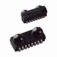
ZHX2022MV040THTR Zilog, ZHX2022MV040THTR Datasheet - Page 15

ZHX2022MV040THTR
Manufacturer Part Number
ZHX2022MV040THTR
Description
Fiber Optic Transmitters, Receivers, Transceivers FIR IrDA 4 MBITS
Manufacturer
Zilog
Datasheet
1.ZHX2022TV040THTR.pdf
(26 pages)
Specifications of ZHX2022MV040THTR
Product
Transceiver
Data Rate
115.2 Kbps
Wavelength
900 nm
Maximum Rise Time
40 ns
Maximum Fall Time
40 ns
Pulse Width Distortion
1.8 us
Operating Supply Voltage
2.7 V to 5.5 V
Maximum Operating Temperature
+ 85 C
Minimum Operating Temperature
- 25 C
Package / Case
UltraSlim
Idle Current, Typ @ 25° C
2mA
Link Range, Low Power
-
Operating Temperature
-25°C ~ 85°C
Orientation
Top View
Shutdown
*
Size
9.7mm x 4.7mm x 4mm
Standards
IrPHY 1.4
Supply Voltage
2.7 V ~ 5.5 V
Lead Free Status
Contains lead
Lead Free Status / RoHS Status
Lead free / RoHS Compliant
Lead Free Status / RoHS Status
Lead free / RoHS Compliant
Available stocks
Company
Part Number
Manufacturer
Quantity
Price
Company:
Part Number:
ZHX2022MV040THTR
Manufacturer:
FUJIKURA
Quantity:
8 000
Recommended Circuit Diagram
PS021802-1005
ZiLOG transceivers integrate a sensitive receiver and a built-in power driver. The
combination of both needs a careful circuit board layout. The use of thin, long,
resistive, and inductive wiring should be avoided. The inputs (Txd, SD, Mode) and
the output Rxd should be directly (DC) coupled to the I/O circuit. See Figure 3 and
Table 7.
The resistor R1 is only necessary for higher operating voltages and elevated tem-
peratures (see derating curve in Figure 6) to avoid too high internal power dissipa-
tion.
The capacitor C1 combined with the resistor R2 is the low pass filter for smoothing
the supply voltage. R2 and C1 are optional and dependent on the quality of the
supply voltage V
voltage during transmission may reduce sensitivity (and transmission range) of
the transceiver.
The placement of these parts is critical. It is strongly recommended to position C1
as near as possible to the transceiver power supply pins.
In addition, when connecting the described circuit to the power supply, low imped-
ance wiring should be used.
Keep in mind that basic RF-design rules for circuit design should be taken into
account. Especially longer signal lines should not be used without termination. For
example, see The Art of Electronics, Paul Horowitz, Wienfield Hill, 1989, Cam-
bridge University Press, ISBN: 0521370957.
CCx
and injected noise. An unstable power supply with dropping
FIR Transceiver
11


