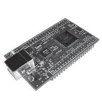
MORPH-IC 1K BLK FTDI, MORPH-IC 1K BLK Datasheet

MORPH-IC 1K BLK
Specifications of MORPH-IC 1K BLK
Related parts for MORPH-IC 1K BLK
MORPH-IC 1K BLK Summary of contents
Page 1
... Morph-IC Data Sheet © Future Technology Devices International Ltd MORPH-IC Data Sheet Revision 1.0 Version 1.0 2004 © Future Technology Devices International Ltd 2004 ...
Page 2
... Training kits consist of an assembled pcb with all the components required for the projects into which you plug a MORPH-IC module ( extra ). Training kits also come with a CD containing VHDL code and software source code for the projects in the kit. 3rd party contributions are also welcome - if you have a MORPH-IC project you would like to share with others please contact us ...
Page 3
... Onboard 6MHz crystal and essential support components for FT2232C. • Onboard 50MHz oscillator as FPGA primary clock. • Onboard LEDs indicate USB driver enumeration and successful FPGA device programming. FIGURE 1 - MORPH-IC BLOCK DIAGRAM ( simplified ) VCC(USB) MOSFET POWER SWITCH CN1 USB FT2232C CONNECTOR USB INTERFACE ...
Page 4
... JP1 and supply +5v from an external PSU to J1 pin 1. The 93C56 EEPROM is pre-programmed at the factory with the correct defaults for MORPH-IC operation. If re-programming this using FTDI’s MPROG utility, great care must be taken or the module and its utilities may cease to work. ...
Page 5
... DLL illustrate how to program the MPSSE as an Altera ACEX series loader. MORPH-IC uses the GPIOL0 pin of the FT2232C to detect / verify the completion of FPGA device configuration and the GPIOL3 pin of the FT2232C to provide a reset to the FPGA via pin 79 ...
Page 6
... IO7 39 40 MORPH-IC has two dedicated 40 pin IO connectors labelled J1 and J2. These are industry standard 40 pin connectors ( two rows of 20 pins ) with square pins on a 0.1in pitch. The two connectors are spaced 1.3in apart ( centre to centre ). See Figure 6 for dimensional drawings. The pinout of the connectors as viewed from above is shown in Figure 5 and the pin descriptions are outlined in Table 1, overleaf ...
Page 7
... TABLE 1 - MORPH-IC IO CONNECTOR PINOUT DESCRIPTION Non-Shared IO Pins Shared IO Pins Dedicated Input Pins FT2232C Handshaking CLKIN RESETIN# VCC ( USB ) ** Note 1 VCC ( Note 1 VCC ( 3. Note 1 GND N/C NOTE 1 - The maximum combined current that can be drawn from these power sources to power external circuitry is 250mA in total supply is required, use VCC ( 5V ) instead of VCC ( USB ) to guarantee meeting USB current draw in USB suspend / sleep state ( < ...
Page 8
... FIGURE 6 - MORPH-IC DIMENSIONAL INFORMATION 0.8in 1.6in 0.43in 0.2in 0.45in MORPH-IC Data Sheet Revision 1.0 CL 0.5in 2.7in 1.9in 0.1in © Future Technology Devices International Ltd 2004 0.1in 0.1in 0.1in 0.1in 0.1in 0.065in 0.35in 0.25in ...
Page 9
... At the time of writing our Sales Network covers over 50 different countries world-wide. Please visit the Sales Network page of our Web site for the contact details of our distributor(s) in your country. Trademarks MORPH-IC and the MORPH-IC Logo are trademarks of Future Technology Devices International Ltd. ACEX 1K and Quartus are trademarks of Altera Corporation. Delphi is a trademark orf Borland Software Corporation. ...


