VUB116-16NO1 IXYS, VUB116-16NO1 Datasheet - Page 6
VUB116-16NO1
Manufacturer Part Number
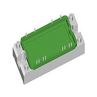
VUB116-16NO1
Description
RECT BRIDGE 3PH 1600V 116A E2
Manufacturer
IXYS
Specifications of VUB116-16NO1
Voltage - Peak Reverse (max)
1600V
Current - Dc Forward (if)
116A
Diode Type
Three Phase - IGBT with Diode
Speed
Standard Recovery >500ns, > 200mA (Io)
Mounting Type
PCB
Package / Case
E2
Channel Type
N
Configuration
Single
Collector-emitter Voltage
1.2kV
Gate To Emitter Voltage (max)
±20V
Mounting
Screw
Operating Temperature (min)
-40C
Operating Temperature Classification
Automotive
Vrrm, Rect, (v)
1600
Idav, Rec, (a)
116
@ Th, Rect, (°c)
-
@ Tc, Rect, (°c)
80
Vces, Igbt, (v)
1200
Ic80, Igbt, (a)
67
Vrrm, Fast Diode, (v)
1200
If(av), Fast Diode, (a)
27
Trr, Fast Diode, (ns)
40
Package Style
E2
Lead Free Status / RoHS Status
Lead free / RoHS Compliant
Reverse Recovery Time (trr)
-
Lead Free Status / RoHS Status
Compliant, Lead free / RoHS Compliant


P
© 2008 IXYS All rights reserved
Z
I
F
tot
thJC
0.01
200
150
100
600
550
500
450
400
350
300
250
200
150
100
K/W
0.1
W
A
50
50
0
0
0
1
0.0
0 .
0
0
Fig. 1 Forward current versus
Fig. 4 Power dissipation vs. direct output current and ambient temperature, sin 180°
Fig. 6 Transient thermal impedance junction to case
1
20
0.5
voltage drop per diode
T
T
40
VJ
VJ
= 125°C
= 25°C
1.0
60
80
1.5
V
F
0
100 120 140
0 .
1
2.0
I
d(AV)M
V
A
I
FSM
Input Rectifier Bridge
600
500
400
300
200
100
A
0
0.001
0
Fig. 2 Surge overload current
20
50Hz, 80% V
40
0
1 .
0.01
60
RRM
80 100 120 140
T
VJ
T
= 45°C
VJ
T
amb
= 150°C
0.1
t
R
t
0.1 K/W
0.3 K/W
0.6 K/W
1.0 K/W
1.5 K/W
2.5 K/W
thA
s
s
:
C
1
1
I
d(AV)
I
2
t
160
140
120
100
A
10
10
A
80
60
40
20
2
0
s
4
3
1
0
Fig. 3 I
Fig. 5 Max. forward current vs.
20 40 60 80 100 120 140
T
T
VJ
VJ
= 150°C
= 45°C
case temperature
2
t versus time per diode
2
VUB 145
3
4 5 6 7 8 9 0
T
C
t
20080513b
6 - 7
ms
C
1
Related parts for VUB116-16NO1
Image
Part Number
Description
Manufacturer
Datasheet
Request
R

Part Number:
Description:
3-Phase Rectifier Bridge with Brake
Manufacturer:
IXYS
Datasheet:

Part Number:
Description:
Three Phase Rectifier Bridge with IGBT and Fast Recovery Diode for Braking System
Manufacturer:
IXYS Corporation
Datasheet:
Part Number:
Description:
HiPerFET Power MOSFETs
Manufacturer:
IXYS Corporation
Datasheet:
Part Number:
Description:
J-K-Type Flip-Flop
Manufacturer:
IXYS Corporation
Datasheet:
Part Number:
Description:
HiPerRF Power MOSFETs
Manufacturer:
IXYS Corporation
Datasheet:
Part Number:
Description:
Rectifier Module for Three Phase Power Factor Correction
Manufacturer:
IXYS Corporation
Datasheet:
Part Number:
Description:
Thyristor Modules Thyristor/Diode Modules
Manufacturer:
IXYS Corporation
Datasheet:
Part Number:
Description:
Thyristor Modules Thyristor/Diode Modules
Manufacturer:
IXYS Corporation
Datasheet:
Part Number:
Description:
Thyristor Modules Thyristor/Diode Modules
Manufacturer:
IXYS Corporation
Datasheet:
Part Number:
Description:
Thyristor Modules Thyristor/Diode Modules
Manufacturer:
IXYS Corporation
Datasheet:
Part Number:
Description:
Thyristor Modules /Diode Modules
Manufacturer:
IXYS Corporation
Datasheet: