EA-EDU-010 Embedded Artists, EA-EDU-010 Datasheet - Page 17
EA-EDU-010
Manufacturer Part Number
EA-EDU-010
Description
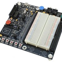
MCU, MPU & DSP Development Tools LPC2138 EDUCATION BRD
Manufacturer
Embedded Artists
Specifications of EA-EDU-010
Processor To Be Evaluated
LPC2138
Data Bus Width
16 bit, 32 bit
Interface Type
I2C, SPI, UART
Core
ARM7TDMI-S
Dimensions
127 mm x 120 mm
Maximum Operating Temperature
+ 85 C
Operating Supply Voltage
3.3 V
Lead Free Status / RoHS Status
Lead free / RoHS Compliant


NXP Semiconductors
LPC2131_32_34_36_38
Product data sheet
6.10.1 Features
6.7.2 Fast I/O features available in LPC213x/01 only
6.8.1 Features
6.8.2 ADC features available in LPC213x/01 only
6.9.1 Features
6.10 UARTs
6.8 10-bit ADC
6.9 10-bit DAC
The LPC2131/32 contain one and the LPC2134/36/38 contain two ADCs. These
converters are single 10-bit successive approximation ADCs with eight multiplexed
channels.
This peripheral is available in the LPC2132/34/36/38 only. The DAC enables the
LPC2132/34/36/38 to generate variable analog output.
The LPC2131/32/34/36/38 each contain two UARTs. In addition to standard transmit and
receive data lines, the LPC2134/36/38 UART1 also provides a full modem control
handshake interface.
•
•
•
•
•
•
•
•
•
•
•
•
•
•
•
•
•
•
Fast I/O registers are located on the ARM local bus for the fastest possible I/O timing.
All GPIO registers are byte addressable.
Entire port value can be written in one instruction.
Mask registers allow single instruction to set or clear any number of bits in one port.
Measurement range of 0 V to 3.3 V.
Each converter capable of performing more than 400000 10-bit samples per second.
Burst conversion mode for single or multiple inputs.
Optional conversion on transition on input pin or Timer Match signal.
Global Start command for both converters (LPC2134/36/38 only).
Every analog input has a dedicated result register to reduce interrupt overhead.
Every analog input can generate an interrupt once the conversion is completed.
10-bit digital to analog converter.
Buffered output.
Power-down mode available.
Selectable speed versus power.
16 B Receive and Transmit FIFOs.
Register locations conform to 16C550 industry standard.
Receiver FIFO trigger points at 1 B, 4 B, 8 B, and 14 B
All information provided in this document is subject to legal disclaimers.
Rev. 5 — 2 February 2011
LPC2131/32/34/36/38
Single-chip 16/32-bit microcontrollers
© NXP B.V. 2011. All rights reserved.
17 of 45
Related parts for EA-EDU-010
Image
Part Number
Description
Manufacturer
Datasheet
Request
R

Part Number:
Description:
MCU, MPU & DSP Development Tools LPC2148 EDUCATION BRD
Manufacturer:
Embedded Artists
Datasheet:

Part Number:
Description:
MCU, MPU & DSP Development Tools LPC2103 EDUCATION BRD
Manufacturer:
Embedded Artists
Datasheet:

Part Number:
Description:
MCU, MPU & DSP Development Tools EXPERIMENT EXPANSION BRD
Manufacturer:
Embedded Artists
Datasheet:

Part Number:
Description:
HEATSINK FOR TO-220 BLACK
Manufacturer:
Ohmite
Datasheet:

Part Number:
Description:
HEATSINK FOR TO-220 BLACK
Manufacturer:
Ohmite
Datasheet:

Part Number:
Description:
HEATSINK FOR TO-220 BLACK
Manufacturer:
Ohmite
Datasheet:

Part Number:
Description:
LCD Graphic Display Modules & Accessories Pure Green Backlight For DOG-M Series
Manufacturer:
ELECTRONIC ASSEMBLY
Datasheet:

Part Number:
Description:
LCD Graphic Display Modules & Accessories Grn LED Backlight For DOG-XL Series
Manufacturer:
ELECTRONIC ASSEMBLY
Datasheet:
Part Number:
Description:
LCD Graphic Display Modules & Accessories Green LED Backlight For DOG-L Series
Manufacturer:
ELECTRONIC ASSEMBLY
Datasheet:

Part Number:
Description:
KIT LPC3141 SODIMM 66X48 200POS
Manufacturer:
Embedded Artists
Datasheet:
Part Number:
Description:
KIT LPC3152 SODIMM 66X48 200POS
Manufacturer:
Embedded Artists
Datasheet:
Part Number:
Description:
BOARD OEM W/LPC2478 MCU
Manufacturer:
Embedded Artists
Datasheet:
Part Number:
Description:
KIT LPC3250 259 WITH QVGA
Manufacturer:
Embedded Artists
Datasheet: