A2F-DEV-KIT Actel, A2F-DEV-KIT Datasheet - Page 7
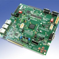
A2F-DEV-KIT
Manufacturer Part Number
A2F-DEV-KIT
Description
MCU, MPU & DSP Development Tools SmartFusion Development Kit
Manufacturer
Actel
Datasheet
1.A2F-DEV-KIT.pdf
(12 pages)
Specifications of A2F-DEV-KIT
Processor To Be Evaluated
A2F200M3F-FGG484
Data Bus Width
32 bit
Interface Type
RS-232, RS-485, Ethernet, USB, I2C, JTAG, SPI
Operating Supply Voltage
5 V
Lead Free Status / RoHS Status
Lead free / RoHS Compliant


System Management
System management continues to gain importance in the design of
all electronic systems, since smaller process geometries drive more
multi-volt devices and are more susceptible to voltage and temperature
fl uctuations. System management tasks focus on maximizing system
uptime, identifying and communicating alert conditions and logging
data and alarm conditions. This can be combined with in-system
diagnostics and prognostics, not only to help debug systems that
have failed, but also to identify potential failures before they arise.
Thus, using a SmartFusion device as a system manager provides the
designer maximum implementation fl exibility.
•
•
•
•
•
Power Management
SmartFusion Mixed Signal Power Manager (MPM) offers a graphically
confi gurable power management solution that performs power rail
monitoring, power sequencing, closed-loop trimming, power-up and
power-down control and event data logging.
•
•
•
•
•
With complete PC-based GUI, source code and a fully
implemented reference design available for use with the
MPM Daughtercard to evaluate the full solution, the MPM
reference design also enables designers to integrate intelligent
confi gurable power management with their own Cortex-M3
fi rmware and FPGA design using SmartFusion devices.
Use the sample sequence engine in the ACE to manage system
health data collection.
Use the post-processing engine in the ACE to manage alert
condition fl ag generation.
Cortex-M3 only needs to make requests to the ACE and respond to
interrupts; no processing cycles needed.
Use FPGA gates for control algorithms when needed.
Communicate through I 2 C, UART, SPI or Ethernet for updates and
reporting.
Manages up to 32 power regulators
8 confi gurable PWM trimming outputs
32 general purpose digital outputs
Data logging to eNVM of critical events
I 2 C and JTAG confi guration updates
Interface
JTAG
Leveraging the considerable processing power of the ACE leaves the
Cortex-M3 and FPGA gates available for running the actual application
or communicating with the outside world. This not only eliminates the
need for multiple ASSP devices to perform system management, but
prevents system management from being an unnecessary burden on
the bill-of-materials (BOM) cost. Selecting SmartFusion devices for
system management provides fl exibility and reliability at the lowest total
cost of ownership (TCO).
Typical Board Using Traditional System Management Solution
EEPROM
EEPROM
DRAM
DRAM
Processor
Processor
32-bit
32-bit
Ch12 Flag
Ch13-16
Ch1 Flag
Flags
Evaluation or Development Kit Board
LED
D12
LED
D1
Nonvolatile
Nonvo
Clock
Clock
Storage
Stor
OSC
OSC
Chip
Chip
Chip
DRAM
DR
R AM
r age
o
latile
SmartFusion
OLED Power Supply
MPM Configuration
ARM Cortex-M3
Registers (NVM)
SmartFusion FPGA
Voltage Display
Digital
Digi
FPGA
FPG
G A
i tal
MPM
Temperature
Temp
Fan Control
Fan
Monitor/
Mo
p
o
Control
nitor/
erature
PWM
PWM
RTC
RTC
CPLD
CPLD
D
Power Enable Ch1
Power Enable Ch4
Sequence
Sequence
Monitor
Monitor
Current
Curr
Current
Power
Powe
Power
MPM Daughter Card
ent
Reg1
Reg4
LED
LED
Power Enable 6-16
Analog in 6-16
Typical System Management
Solution Using SmartFusion
Reg1 3.3 V
Reg4 5.0 V
Rail 1 Voltage
Rail 4 Voltage
V out 1
V out 4
7
Related parts for A2F-DEV-KIT
Image
Part Number
Description
Manufacturer
Datasheet
Request
R

Part Number:
Description:
MCU, MPU & DSP Development Tools Smart Fusion Eval Kit
Manufacturer:
Actel
Datasheet:

Part Number:
Description:
MCU, MPU & DSP Development Tools SmartFusion Motor Control Dev Kit
Manufacturer:
Actel

Part Number:
Description:
MCU, MPU & DSP Development Tools Silicon Sculptor Programming Mod
Manufacturer:
Actel
Part Number:
Description:
MCU, MPU & DSP Development Tools InSystem Programming ProASICPLUS Devices
Manufacturer:
Actel
Part Number:
Description:
Programming Socket Adapters & Emulators PQ160 Module
Manufacturer:
Actel
Part Number:
Description:
Programming Socket Adapters & Emulators Axcelerator Adap Module Kit
Manufacturer:
Actel
Part Number:
Description:
Programming Socket Adapters & Emulators Evaluation
Manufacturer:
Actel
Part Number:
Description:
Programming Socket Adapters & Emulators AFDX Solutions
Manufacturer:
Actel
Part Number:
Description:
Programming Socket Adapters & Emulators SILICON SCULPTOR ADAPTER MODULE
Manufacturer:
Actel
Datasheet:
Part Number:
Description:
Programming Socket Adapters & Emulators Axcelerator Adap Module Kit
Manufacturer:
Actel
Part Number:
Description:
Programming Socket Adapters & Emulators Evaluation
Manufacturer:
Actel
Part Number:
Description:
Programming Socket Adapters & Emulators Silicon Sculptor Software
Manufacturer:
Actel
Part Number:
Description:
Programming Socket Adapters & Emulators InSystem Programming ProASICPLUS Devices
Manufacturer:
Actel
Part Number:
Description:
Programming Socket Adapters & Emulators Evaluation
Manufacturer:
Actel