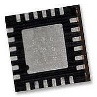
ITG-3200 INVENSENSE, ITG-3200 Datasheet - Page 18

ITG-3200
Manufacturer Part Number
ITG-3200
Description
IC, GYRO, TRI-AXIS, +/-2000 DEG/S
Manufacturer
INVENSENSE
Datasheet
1.ITG-3200.pdf
(39 pages)
Specifications of ITG-3200
No. Of Axes
3
Sensor Case Style
QFN
No. Of Pins
24
Supply Voltage Range
2.1V To 3.6V
Operating Temperature Range
-40°C To +85°C
Interface
I2C, Serial
Interface Type
I2C, Serial
Rohs Compliant
Yes
Lead Free Status / RoHS Status
Lead free / RoHS Compliant
Available stocks
Company
Part Number
Manufacturer
Quantity
Price
Part Number:
ITG-3200
Manufacturer:
INVENSE
Quantity:
20 000
6
6.1
The internal registers and memory of the ITG-3200 can be accessed using I
Serial Interface
6.1.1
I
open-drain and bi-directional. In a generalized I
slave. The master device puts the slave address on the bus, and the slave device with the matching address
acknowledges the master.
The ITG-3200 always operates as a slave device when communicating to the system processor, which thus acts as the
master. SDA and SCL lines typically need pull-up resistors to VDD. The maximum bus speed is 400kHz.
The slave address of the ITG-3200 devices is b110100X which is 7 bits long. The LSB bit of the 7 bit address is
determined by the logic level on pin 9. This allows two ITG-3200 devices to be connected to the same I
used in this configuration, the address of the one of the devices should be b1101000 (pin 9 is logic low) and the address
of the other should be b1101001 (pin 9 is logic high). The I
I
START (S) and STOP (P) Conditions
Communication on the I
HIGH-to-LOW transition of the SDA line while SCL line is HIGH (see figure below). The bus is considered to be busy
until the master puts a STOP condition (P) on the bus, which is defined as a LOW to HIGH transition on the SDA line
while SCL is HIGH (see figure below).
Additionally, the bus remains busy if a repeated START (Sr) is generated instead of a STOP condition.
2
2
C is a two wire interface comprised of the signals serial data (SDA) and serial clock (SCL). In general, the lines are
C Communications Protocol
Digital Interface
Pin Number
I
2
C Serial Interface
I
2
C Interface
23
24
8
9
SDA
SCL
START condition
2
C bus starts when the master puts the START condition (S) on the bus, which is defined as a
Pin Name
VLOGIC
AD0
SDA
SCL
S
ITG-3200 Product Specification
Pin Description
Digital IO supply voltage. VLOGIC must be ≤ VDD at all times.
I
I
I
2
2
2
C Slave Address LSB
C serial clock
C serial data
START and STOP Conditions
2
C interface implementation, attached devices can be a master or a
2
C address is stored in register 0 (WHO_AM_I register).
2
C at up to 400kHz.
Document Number: PS-ITG-3200A-00-01.4
Revision: 1.4
Release Date: 03/30/2010
STOP condition
P
18 of 39
2
C bus. When


