74LVC16244AEV/G:55 NXP Semiconductors, 74LVC16244AEV/G:55 Datasheet
74LVC16244AEV/G:55
Specifications of 74LVC16244AEV/G:55
74LVC16244AEV/G-S
935281135551
Available stocks


Related parts for 74LVC16244AEV/G:55


74LVC16244AEV/G:55 Summary of contents
Page 1
V input/output tolerant; 3-state Rev. 09 — 18 March 2010 1. General description The 74LVC16244A; 74LVCH16244A are 16-bit non-inverting buffer/line drivers with 3-state bus compatible outputs. The device can be used as four 4-bit ...
Page 2
... NXP Semiconductors 3. Ordering information Table 1. Ordering information Type number Temperature range Package −40 °C to +125 °C 74LVC16244ADL 74LVCH16244ADL −40 °C to +125 °C 74LVC16244ADGG 74LVCH16244ADGG −40 °C to +125 °C 74LVC16244AEV 74LVCH16244AEV −40 °C to +125 °C 74LVC16244ABQ 74LVCH16244ABQ 4. Functional diagram 1A0 1Y0 47 2 1A1 ...
Page 3
... NXP Semiconductors Fig 3. Bus hold circuit 5. Pinning information 5.1 Pinning 1OE 1 2 1Y0 3 1Y1 GND 4 1Y2 5 1Y3 2Y0 2Y1 9 GND 10 2Y2 11 2Y3 12 74LVC16244A 13 3Y0 74LVCH16244A 3Y1 14 GND 15 3Y2 16 3Y3 4Y0 19 4Y1 20 GND 21 4Y2 22 23 4Y3 24 4OE Fig 4. Pin configuration SOT370-1 (SSOP48) and ...
Page 4
... NXP Semiconductors terminal 1 index area (1) The die substrate is attached to this pad using conductive die attach material. It can not be used as a supply pin or input. Fig 6. Pin configuration SOT1134-1 (HXQFN60U) 74LVC_LVCH16244A_9 Product data sheet 74LVC16244A; 74LVCH16244A 16-bit buffer/line driver input/output tolerant; 3-state D1 A32 ...
Page 5
... NXP Semiconductors 5.2 Pin description Table 2. Pin description Symbol Pin SOT370-1 and SOT362-1 1OE, 2OE, 1, 48, 25, 24 3OE, 4OE 1Y0 to 1Y3 2Y0 to 2Y3 8, 9, 11, 12 3Y0 to 3Y3 13, 14, 16, 17 4Y0 to 4Y3 19, 20, 22, 23 GND 4, 10, 15, 21, 28, 34, 39 18, 31 1A0 to 1A3 47, 46, 44, 43 ...
Page 6
... NXP Semiconductors 7. Limiting values Table 4. Limiting values In accordance with the Absolute Maximum Rating System (IEC 60134). Voltages are referenced to GND (ground = 0 V). Symbol Parameter V supply voltage CC I input clamping current IK V input voltage I I output clamping current OK V output voltage O I output current ...
Page 7
... NXP Semiconductors 9. Static characteristics Table 6. Static characteristics At recommended operating conditions. Voltages are referenced to GND (ground = 0 V). Symbol Parameter Conditions V HIGH-level input voltage LOW-level input voltage HIGH-level output voltage LOW-level output voltage input leakage current I OFF-state output current power-off leakage V OFF I current ...
Page 8
... NXP Semiconductors Table 6. Static characteristics At recommended operating conditions. Voltages are referenced to GND (ground = 0 V). Symbol Parameter Conditions I bus hold HIGH V BHHO CC overdrive current [1] All typical values are measured at V [2] The bus hold circuit is switched off when V [3] For I/O ports the parameter I includes the input leakage current ...
Page 9
... NXP Semiconductors Table 7. Dynamic characteristics Voltages are referenced to GND (ground = 0 V). For test circuit see Symbol Parameter Conditions C power per buffer dissipation outputs enabled capacitance outputs disabled [ the same as t and PLH PHL t is the same as t and PZL PZH t is the same as t and t ...
Page 10
... NXP Semiconductors nOE input output LOW-to-OFF OFF-to-LOW output HIGH-to-OFF OFF-to-HIGH Measurement points are given in Logic levels: V and Fig 8. 3-state enable and disable times. Table 8. Measurement points Supply voltage Input 1 2.7 V 2 3.6 V 2.7 V 74LVC_LVCH16244A_9 Product data sheet 74LVC16244A; 74LVCH16244A 16-bit buffer/line driver input/output tolerant; 3-state ...
Page 11
... NXP Semiconductors Test data is given in Table Definitions for test circuit Load resistance Load capacitance including jig and probe capacitance Termination resistance should be equal to output impedance External voltage for measuring switching times. EXT Fig 9. Load circuit for measuring switching times Table 9. Test data ...
Page 12
... NXP Semiconductors 12. Package outline SSOP48: plastic shrink small outline package; 48 leads; body width 7 pin 1 index 1 e DIMENSIONS (mm are the original dimensions) A UNIT max. 0.4 2.35 mm 2.8 0.25 0.2 2.20 Note 1. Plastic or metal protrusions of 0.25 mm maximum per side are not included. OUTLINE ...
Page 13
... NXP Semiconductors TSSOP48: plastic thin shrink small outline package; 48 leads; body width 6 pin 1 index 1 DIMENSIONS (mm are the original dimensions). A UNIT max. 0.15 1.05 mm 1.2 0.25 0.05 0.85 Notes 1. Plastic or metal protrusions of 0.15 mm maximum per side are not included. 2. Plastic interlead protrusions of 0.25 mm maximum per side are not included. ...
Page 14
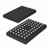
... NXP Semiconductors VFBGA56: plastic very thin fine-pitch ball grid array package; 56 balls; body 4 0.65 mm ball A1 index area ball A1 1 index area DIMENSIONS (mm are the original dimensions) A UNIT max. 0.3 0.7 0. 0.2 0.6 0.35 OUTLINE VERSION IEC SOT702-1 Fig 12. Package outline SOT702-1 (VFBGA56) ...
Page 15
... NXP Semiconductors HXQFN60U: plastic thermal enhanced extremely thin quad flat package; no leads; 60 terminals; UTLP based; body 0.5 mm terminal 1 index area A10 terminal 1 index area D1 Dimensions Unit max 0.50 0.05 0.35 4.1 mm nom 0.48 0.02 0.30 4.0 min 0.46 0.00 0.25 3.9 ...
Page 16
... NXP Semiconductors 13. Abbreviations Table 10. Abbreviations Acronym Description CMOS Complementary Metal Oxide Semiconductor DUT Device Under Test ESD ElectroStatic Discharge HBM Human Body Model MM Machine Model TTL Transistor-Transistor Logic 14. Revision history Table 11. Revision history Document ID Release date 74LVC_LVCH16244A_9 20100318 • Modifications: 74LVC_LVCH16244A_8 ...
Page 17
... In no event shall NXP Semiconductors be liable for any indirect, incidental, punitive, special or consequential damages (including - without limitation - lost profits, lost savings, business interruption, costs related to the removal or ...
Page 18
... NXP Semiconductors 16. Contact information For more information, please visit: For sales office addresses, please send an email to: 74LVC_LVCH16244A_9 Product data sheet 74LVC16244A; 74LVCH16244A 16-bit buffer/line driver input/output tolerant; 3-state http://www.nxp.com salesaddresses@nxp.com All information provided in this document is subject to legal disclaimers. Rev. 09 — 18 March 2010 © ...
Page 19
... NXP Semiconductors 17. Contents 1 General description . . . . . . . . . . . . . . . . . . . . . . 1 2 Features and benefits . . . . . . . . . . . . . . . . . . . . 1 3 Ordering information . . . . . . . . . . . . . . . . . . . . . 2 4 Functional diagram . . . . . . . . . . . . . . . . . . . . . . 2 5 Pinning information . . . . . . . . . . . . . . . . . . . . . . 3 5.1 Pinning . . . . . . . . . . . . . . . . . . . . . . . . . . . . . . . 3 5.2 Pin description . . . . . . . . . . . . . . . . . . . . . . . . . 5 6 Functional description . . . . . . . . . . . . . . . . . . . 5 7 Limiting values Recommended operating conditions Static characteristics Dynamic characteristics . . . . . . . . . . . . . . . . . . 8 11 Waveforms . . . . . . . . . . . . . . . . . . . . . . . . . . . . . 9 12 Package outline . . . . . . . . . . . . . . . . . . . . . . . . 12 13 Abbreviations ...