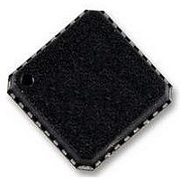
ADAU1961WBCPZ Analog Devices Inc, ADAU1961WBCPZ Datasheet - Page 49

ADAU1961WBCPZ
Manufacturer Part Number
ADAU1961WBCPZ
Description
IC STEREO AUD CODEC LP 32LFCSP
Manufacturer
Analog Devices Inc
Type
Audio Codecr
Datasheet
1.ADAU1961WBCPZ-RL.pdf
(76 pages)
Specifications of ADAU1961WBCPZ
Data Interface
Serial
Resolution (bits)
24 b
Number Of Adcs / Dacs
2 / 2
Sigma Delta
No
S/n Ratio, Adcs / Dacs (db) Typ
99 / 101
Dynamic Range, Adcs / Dacs (db) Typ
99 / 101
Voltage - Supply, Analog
2.97 V ~ 3.63 V
Operating Temperature
-40°C ~ 105°C
Mounting Type
Surface Mount
Package / Case
32-VFQFN, CSP Exposed Pad
Audio Codec Type
Stereo
No. Of Adcs
2
No. Of Dacs
2
No. Of Input Channels
2
No. Of Output Channels
2
Adc / Dac Resolution
24bit
Adcs / Dacs Signal To Noise Ratio
101dB
Sampling Rate
96kSPS
No. Of
RoHS Compliant
Rohs Compliant
Yes
Lead Free Status / RoHS Status
Lead free / RoHS Compliant
Available stocks
Company
Part Number
Manufacturer
Quantity
Price
Company:
Part Number:
ADAU1961WBCPZ
Manufacturer:
AD
Quantity:
2 469
Part Number:
ADAU1961WBCPZ
Manufacturer:
ADI/亚德诺
Quantity:
20 000
R7: Record Mixer Right (Mixer 2) Control 1, 16,397 (0x400D)
This register controls the gain boost of the right channel differential PGA input and the gain for the right channel auxiliary input in the
record path. The right channel record mixer is referred to as Mixer 2.
Bit 7
Table 32. Record Mixer Right (Mixer 2) Control 1 Register
Bits
[4:3]
[2:0]
R8: Left Differential Input Volume Control, 16,398 (0x400E)
This register enables the differential path and sets the volume control for the left differential PGA input.
Bit 7
Table 33. Left Differential Input Volume Control Register
Bits
[7:2]
1
0
Bit Name
RDBOOST[1:0]
MX2AUXG[2:0]
Bit Name
LDVOL[5:0]
LDMUTE
LDEN
Bit 6
Bit 6
Reserved
Right single-ended auxiliary input gain from the RAUX pin in the record path, input to Mixer 2.
Description
Right channel differential PGA input gain boost, input to Mixer 2. The right differential input uses the RINP
(positive signal) and RINN (negative signal) pins.
Setting
00
01
10
11
Setting
000
001
010
011
100
101
110
111
Description
Left channel differential PGA input volume control. The left differential input uses the LINP (positive signal) and
LINN (negative signal) pins. Each step corresponds to a 0.75 dB increase in gain. See Table 69 for a complete list
of the volume settings.
Setting
000000
000001
…
010000
…
111110
111111
Left differential input mute control.
0 = mute (default).
1 = unmute.
Left differential PGA enable. When enabled, the LINP and LINN pins are used as a full differential pair. When
disabled, these two pins are configured as two single-ended inputs with the signals routed around the PGA.
0 = disabled (default).
1 = enabled.
Bit 5
Bit 5
LDVOL[5:0]
Bit 4
Bit 4
Gain Boost
Mute (default)
0 dB
20 dB
Reserved
Auxiliary Input Gain
Mute (default)
−12 dB
−9 dB
−6 dB
−3 dB
0 dB
3 dB
6 dB
Volume
−12 dB (default)
−11.25 dB
…
0 dB
…
34.5 dB
35.25 dB
Rev. 0 | Page 49 of 76
RDBOOST[1:0]
Bit 3
Bit 3
Bit 2
Bit 2
Bit 1
Bit 1
LDMUTE
MX2AUXG[2:0]
ADAU1961
Bit 0
Bit 0
LDEN


