AD9788-EBZ Analog Devices Inc, AD9788-EBZ Datasheet - Page 42
AD9788-EBZ
Manufacturer Part Number
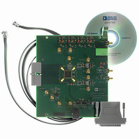
AD9788-EBZ
Description
BOARD EVAL FOR AD9788
Manufacturer
Analog Devices Inc
Series
TxDAC®r
Datasheet
1.AD9785BSVZ.pdf
(64 pages)
Specifications of AD9788-EBZ
Design Resources
Powering the AD9788 Using ADP2105 for Increased Efficiency (CN0141)
Number Of Dac's
2
Number Of Bits
16
Outputs And Type
2, Differential
Sampling Rate (per Second)
800M
Data Interface
Serial
Settling Time
22ms
Dac Type
Current
Voltage Supply Source
Analog and Digital
Operating Temperature
-40°C ~ 85°C
Utilized Ic / Part
AD9788
Silicon Manufacturer
Analog Devices
Application Sub Type
DAC
Kit Application Type
Data Converter
Silicon Core Number
AD9788
Kit Contents
Board
Development Tool Type
Hardware - Eval/Demo Board
Lead Free Status / RoHS Status
Lead free / RoHS Compliant


AD9785/AD9787/AD9788
DEVICE SYNCHRONIZATION
System demands may impose two different requirements for
synchronization. Some systems require multiple DACs to be
synchronized to each other, for example, a system that supports
transmit diversity or beamforming, where multiple antennas are
used to transmit a correlated signal. In this case, the DAC outputs
need to be phase aligned with each other, but there may not be a
requirement for the DAC outputs to be aligned with a system-
level reference clock. In systems with a time division multiplexing
transmit chain, one or more DACs may be required to be
synchronized with a system-level reference clock.
Multiple devices are considered synchronized to each other
when the state of the clock generation state machines is
identical for all parts and the NCO phase accumulator is
identical for all parts. Devices are considered synchronized to a
system clock when there is a fixed and known relationship
between the clock generation state machine and the NCO phase
accumulator of the device to a particular clock edge of the
system clock. The AD9785/AD9787/AD9788 support two
modes of operation, pulse mode and PN code mode, for
synchronizing devices under these two conditions.
SYNCHRONIZATION LOGIC OVERVIEW
Figure 60 shows a block diagram of the on-chip synchronization
receive logic. There are two different modes of operation for the
multichip synchronization feature: pulse mode and pseudorandom
noise code (PN code) modulation/demodulation mode. The basic
function of these two modes is to initialize the internal clock
generation state machine and the NCO phase accumulator
upon the application of external signals to the device.
The receive logic responsible for initializing the clock gener-
ation state machine generates a single DACCLK cycle-wide
Rev. A | Page 42 of 64
initialization pulse that sets the clock generation state machine
logic to a known state. In pulse mode, this pulse is generated at
every rising edge of the SYNC_I inputs. In PN code mode, the
pulse is generated every time the correct code sequence is
received on the SYNC_I inputs.
This initialization pulse loads the clock generation state machine
with the Clock State [3:0] value (Register 0x03, Bits [7:4]) as its
next state. If the initialization pulse from the synchronization
logic is generated properly, it is active for one DAC clock cycle,
every 32 (or multiple of 32) DAC clock cycles. Because the clock
generation state machine has 32 states operating at the DACCLK
rate, every initialization pulse received after the first pulse loads
the current state (the state to which the state machine is already
set), maintaining the proper clock operation of the device.
The Clock State [3:0] value is the state to which the clock
generation state machine resets upon initialization. By varying
this value, the timing of the internal clocks, with respect to
the SYNC_I signal, can be adjusted. Every increment of the
Clock State [3:0] value advances the internal clocks by one
DACCLK period.
The NCO phase accumulators can be initialized in pulse mode
or PN code mode. In pulse mode, a simultaneous strobe signal
must be sent to the TXENABLE pin of all devices that is
synchronous to the DATACLK signal. This signal resets the
phase accumulator of the NCOs across all devices, effectively
synchronizing the NCOs.
In PN code mode, the phase information of the master device is
sent to the slave devices by the SYNC_I signal. The slave devices
decode this phase information and automatically initialize their
NCO phase accumulators to match the master device.
Related parts for AD9788-EBZ
Image
Part Number
Description
Manufacturer
Datasheet
Request
R

Part Number:
Description:
Dual 16B, 1.0 GSPS TxDAC
Manufacturer:
Analog Devices Inc
Datasheet:

Part Number:
Description:
±1.7g Dual-Axis IMEMS Accelerometer Evaluation Board
Manufacturer:
Analog Devices Inc
Datasheet:
Part Number:
Description:
Inertial Sensor Evaluation System
Manufacturer:
Analog Devices Inc
Datasheet:
Part Number:
Description:
Manufacturer:
Analog Devices Inc
Datasheet:
Part Number:
Description:
Manufacturer:
Analog Devices Inc
Datasheet:
Part Number:
Description:
Manufacturer:
Analog Devices Inc
Datasheet:
Part Number:
Description:
Manufacturer:
Analog Devices Inc
Datasheet:
Part Number:
Description:
Manufacturer:
Analog Devices Inc
Datasheet:
Part Number:
Description:
Manufacturer:
Analog Devices Inc
Datasheet:
Part Number:
Description:
Manufacturer:
Analog Devices Inc
Datasheet:
Part Number:
Description:
Manufacturer:
Analog Devices Inc
Datasheet:
Part Number:
Description:
Manufacturer:
Analog Devices Inc
Datasheet:
Part Number:
Description:
Manufacturer:
Analog Devices Inc
Datasheet: