AD9788-EBZ Analog Devices Inc, AD9788-EBZ Datasheet - Page 45
AD9788-EBZ
Manufacturer Part Number
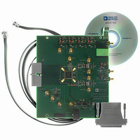
AD9788-EBZ
Description
BOARD EVAL FOR AD9788
Manufacturer
Analog Devices Inc
Series
TxDAC®r
Datasheet
1.AD9785BSVZ.pdf
(64 pages)
Specifications of AD9788-EBZ
Design Resources
Powering the AD9788 Using ADP2105 for Increased Efficiency (CN0141)
Number Of Dac's
2
Number Of Bits
16
Outputs And Type
2, Differential
Sampling Rate (per Second)
800M
Data Interface
Serial
Settling Time
22ms
Dac Type
Current
Voltage Supply Source
Analog and Digital
Operating Temperature
-40°C ~ 85°C
Utilized Ic / Part
AD9788
Silicon Manufacturer
Analog Devices
Application Sub Type
DAC
Kit Application Type
Data Converter
Silicon Core Number
AD9788
Kit Contents
Board
Development Tool Type
Hardware - Eval/Demo Board
Lead Free Status / RoHS Status
Lead free / RoHS Compliant


Table 32 shows the register settings required to enable the pulse
mode synchronization feature.
Table 32. Register Settings for Enabling Pulse Sync Mode
Register
0x01
0x03
Synchronization Timing Error Detection
The synchronization logic has error detection circuitry similar
to the input data timing. The Sync Timing Margin [3:0] variable
(Register 0x03) determines the setup and hold margin that the
synchronization interface needs for the SYNC timing error IRQ
to remain inactive (show error-free operation). Thus, the SYNC
timing error IRQ is set whenever the setup and hold margins
drop below the Sync Timing Margin [3:0] value and does not
necessarily indicate that the SYNC_I input was latched incorrectly.
When a SYNC timing error IRQ is set, corrective action can
restore the timing margin. The device can be configured for
manual mode sync error monitoring and error correction.
Follow these steps to monitor SYNC_I setup and hold timing
margins in manual mode:
1.
2.
3.
4.
5.
Set sync error check mode (Register 0x03, Bit 18) = 0
(manual check mode).
Set Sync Timing Margin [3:0] (Register 0x03, Bits [3:0]) =
0000 (timing margin to minimum value).
Set SYNC_I Delay [4:0] (Register 0x03, Bits [23:19]) =
00000 (SYNC_I delay line to minimum value).
Set sync port IRQ enable (Register 0x09, Bit 0) = 1.
Write 1 to sync timing error IRQ (Register 0x09, Bit 6)
to clear.
Bit
[13]
[12]
[11]
[26]
[25]
[10]
SYSTEM CLOCK
Parameter
PN code sync enable
Sync mode select
Pulse sync enable
SYNC_I enable
SYNC_O enable
Set high
Figure 64. Multichip Synchronization in PN Code Mode
CLOCK DRIVER
CLOCK DRIVER
LOW SKEW
LOW SKEW
Value
0
0
1
1
0
1
Rev. A | Page 45 of 64
MATCHED
LENGTH TRACES
MATCHED
LENGTH TRACES
6.
7.
SYNCHRONIZING MULTIPLE DEVICES TO EACH
OTHER
The AD9785/AD9787/AD9788 synchronization engine uses
a PN code synchronization scheme to align multiple devices
within a system to the same DAC clock edge. The PN code
scheme synchronizes all the internal clocks, as well as the phase
accumulator of the NCO for all devices. With this scheme, one
device functions as the master, and the remainder of the devices
are configured as slaves.
The master device generates the PN encoded signal and drives
the signal out on the SYNC_O (SYNC_O+/SYNC_O−) output
pins. This signal is then sent to the SYNC_I (SYNC_I+/
SYNC_I−) inputs of all the slave devices and to itself. The slave
devices receive the code from the master and demodulate the
signal to produce a synchronization pulse every time a valid
code is received. The encoded signal of every device must be
sampled on the same DAC clock edge for the devices to be
properly synchronized. Therefore, it is extremely important that
the REFCLK signals arrive at all the devices with as little skew
between them as possible. In addition, the SYNC_I signals must
arrive at all the devices with as little skew as possible. At high
DACCLK frequencies, this requires using low skew clock
distribution devices to deliver the REFCLK and SYNC_I signals
and paying careful attention to printed circuit board signal
routing to equalize the trace lengths of these signals.
Read back sync timing error IRQ and sync timing error
type (Register 0x09, Bit 4). If sync timing error IRQ is high,
a sampling error has occurred, and sync timing error type
indicates whether the sampling error is due to a setup time
violation or a hold time violation.
Adjust the SYNC_I Delay [4:0] value until the sync timing
error IRQ is no longer present.
REFCLK
TXENABLE
SYNC_I
REFCLK
TXENABLE
SYNC_I
SYNC_O
AD9785/AD9787/AD9788
OUT
OUT
Related parts for AD9788-EBZ
Image
Part Number
Description
Manufacturer
Datasheet
Request
R

Part Number:
Description:
Dual 16B, 1.0 GSPS TxDAC
Manufacturer:
Analog Devices Inc
Datasheet:

Part Number:
Description:
±1.7g Dual-Axis IMEMS Accelerometer Evaluation Board
Manufacturer:
Analog Devices Inc
Datasheet:
Part Number:
Description:
Inertial Sensor Evaluation System
Manufacturer:
Analog Devices Inc
Datasheet:
Part Number:
Description:
Manufacturer:
Analog Devices Inc
Datasheet:
Part Number:
Description:
Manufacturer:
Analog Devices Inc
Datasheet:
Part Number:
Description:
Manufacturer:
Analog Devices Inc
Datasheet:
Part Number:
Description:
Manufacturer:
Analog Devices Inc
Datasheet:
Part Number:
Description:
Manufacturer:
Analog Devices Inc
Datasheet:
Part Number:
Description:
Manufacturer:
Analog Devices Inc
Datasheet:
Part Number:
Description:
Manufacturer:
Analog Devices Inc
Datasheet:
Part Number:
Description:
Manufacturer:
Analog Devices Inc
Datasheet:
Part Number:
Description:
Manufacturer:
Analog Devices Inc
Datasheet:
Part Number:
Description:
Manufacturer:
Analog Devices Inc
Datasheet: