AD9788-EBZ Analog Devices Inc, AD9788-EBZ Datasheet - Page 46
AD9788-EBZ
Manufacturer Part Number
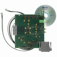
AD9788-EBZ
Description
BOARD EVAL FOR AD9788
Manufacturer
Analog Devices Inc
Series
TxDAC®r
Datasheet
1.AD9785BSVZ.pdf
(64 pages)
Specifications of AD9788-EBZ
Design Resources
Powering the AD9788 Using ADP2105 for Increased Efficiency (CN0141)
Number Of Dac's
2
Number Of Bits
16
Outputs And Type
2, Differential
Sampling Rate (per Second)
800M
Data Interface
Serial
Settling Time
22ms
Dac Type
Current
Voltage Supply Source
Analog and Digital
Operating Temperature
-40°C ~ 85°C
Utilized Ic / Part
AD9788
Silicon Manufacturer
Analog Devices
Application Sub Type
DAC
Kit Application Type
Data Converter
Silicon Core Number
AD9788
Kit Contents
Board
Development Tool Type
Hardware - Eval/Demo Board
Lead Free Status / RoHS Status
Lead free / RoHS Compliant


AD9785/AD9787/AD9788
Table 33 lists the register settings required to enable the PN
code mode synchronization feature.
Table 33. Register Settings for Enabling PN Code Mode
Register
0x01
0x03
To verify that the devices have successfully synchronized, read
back the sync lock status bit on all devices (Register 0x09,
Bit 10). The sync lock status bit should read back as 1 on all
devices. Next, read back the sync lock lost status bit on all
devices (Register 0x09, Bit 11). The sync lock lost status bit
should read back as 0 on all devices. To clear the sync lock lost
status bit, set the clear lock indicator bit to 1, followed by a 0
(Register 0x09, Bit 12).
Because the SYNC_O signal generated by the master is spread
over many bits, this method of synchronization is very robust.
Any individual bits that may become corrupted or somehow
misread by the slave device usually have no effect on the
synchronization of the device. If the devices do not reliably
synchronize, there are several options for correcting the situation.
The SYNC_O Delay [4:0] value (Register 0x03, Bits [15:11]) on
the master device can be used to adjust the timing in 80 ps steps
effective across all devices. In addition, the SYNC_O polarity bit
(Register 0x03, Bit 9) on the master device can be set to provide
a delay of one half the DACCLK period. The SYNC_I Delay [4:0]
bits (Register 0x03, Bits [23:19]) can be used to adjust the
timing on a single slave device in 80 ps steps.
Bit
[13]
[12]
[11]
[31:27]
[26]
[25]
[10]
Parameter
PN code sync enable
Sync mode select
Pulse sync enable
Correlate Threshold
[4:0]
SYNC_I enable
SYNC_O enable
Set high
Value
1
1
0
10000
1
0 (slave devices)
1 (master device)
1
Rev. A | Page 46 of 64
The Correlate Threshold [4:0] value (Register 0x03,
Bits [31:27]) indicates how closely the code of the received
SYNC_I signal is to the expected code. A high threshold
requires a closer match of the encoded signal to set the
sync lock status bit; a lower value reduces the matching
requirements to set the sync lock status bit.
Increasing the Correlate Threshold [4:0] value makes the part
more resistant to false synchronization locks but requires a
lower bit error rate on the SYNC_I input to maintain locked
status. Decreasing the Correlate Threshold [4:0] value makes
the part more susceptible to false synchronization locks, but
maintains a locked status in the face of a higher bit error rate
on the SYNC_I input (that is, it is more noise resistant). The
recommended value for Correlate Threshold [4:0] is the default
value of 16.
INTERRUPT REQUEST OPERATION
The IRQ pin (Pin 71) acts as an alert that the device has
experienced a timing error and that it should be queried (by
reading Register 0x09) to determine the exact fault condition.
The IRQ pin is an open-drain, active low output. The IRQ pin
should be pulled high external to the device. This pin may be
tied to the IRQ pins of other devices with open-drain outputs to
wire-OR these pins together.
There are two different error flags that can trigger an interrupt
request: a data timing error or a sync timing error. By default,
when either or both of these error flags are set, the IRQ pin is
active low. Either or both of these error flags can be masked to
prevent them from activating an interrupt on the IRQ pin.
The error flags are latched and remain active until the flag bits
are overwritten.
Related parts for AD9788-EBZ
Image
Part Number
Description
Manufacturer
Datasheet
Request
R

Part Number:
Description:
Dual 16B, 1.0 GSPS TxDAC
Manufacturer:
Analog Devices Inc
Datasheet:

Part Number:
Description:
±1.7g Dual-Axis IMEMS Accelerometer Evaluation Board
Manufacturer:
Analog Devices Inc
Datasheet:
Part Number:
Description:
Inertial Sensor Evaluation System
Manufacturer:
Analog Devices Inc
Datasheet:
Part Number:
Description:
Manufacturer:
Analog Devices Inc
Datasheet:
Part Number:
Description:
Manufacturer:
Analog Devices Inc
Datasheet:
Part Number:
Description:
Manufacturer:
Analog Devices Inc
Datasheet:
Part Number:
Description:
Manufacturer:
Analog Devices Inc
Datasheet:
Part Number:
Description:
Manufacturer:
Analog Devices Inc
Datasheet:
Part Number:
Description:
Manufacturer:
Analog Devices Inc
Datasheet:
Part Number:
Description:
Manufacturer:
Analog Devices Inc
Datasheet:
Part Number:
Description:
Manufacturer:
Analog Devices Inc
Datasheet:
Part Number:
Description:
Manufacturer:
Analog Devices Inc
Datasheet:
Part Number:
Description:
Manufacturer:
Analog Devices Inc
Datasheet: