VS6502V015/T2 STMicroelectronics, VS6502V015/T2 Datasheet - Page 20
VS6502V015/T2
Manufacturer Part Number
VS6502V015/T2
Description
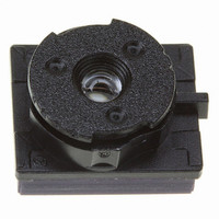
SENSOR COLOR VGA CMOS SMOP
Manufacturer
STMicroelectronics
Type
CMOS Imagingr
Datasheet
1.VS6502V015T2.pdf
(48 pages)
Specifications of VS6502V015/T2
Pixel Size
5.6µm x 5.6µm
Active Pixel Array
644H x 484V
Frames Per Second
30
Voltage - Supply
2.6 V ~ 3.6 V
Package / Case
SMOP2
Lead Free Status / RoHS Status
Lead free / RoHS Compliant
Other names
497-3884-1
Available stocks
Company
Part Number
Manufacturer
Quantity
Price

Part Number:
VS6502V015/T2
Manufacturer:
ST
Quantity:
20 000


Serial Control Bus
3.2.2
20/48
The byte following the address byte contains the address of the first data byte (also referred to as
the index). The serial interface can address up to 128 byte registers.
Message interpretation
All serial interface communications with the sensor must begin with a start condition. If the start
condition is followed by a valid address byte then further communications can take place. The
sensor will acknowledge the receipt of a valid address by driving the sda wire low. The state of the
read/~write bit (LSB of the address byte) is stored and the next byte of data, sampled from sda, can
be interpreted.
During a write sequence the second byte sent to the sensor is an index and is used to point to one
of the internal registers.
The master can therefore send data bytes continuously to the slave until the slave fails to provide
an acknowledge or the master terminates the write communication with a stop condition or sends a
repeated start (Sr).
As data is received by the slave, it is written bit by bit to a serial/parallel register. After each data
byte has been received by the slave, an acknowledge is generated, the data is then stored in the
internal register addressed by the current index.
During a read message, the current index is read out in the byte following the device address byte.
The next byte read from the slave device includes the contents of the register addressed by the
current index. The contents of this register are then parallel loaded into the serial/parallel register
and clocked out of the device by scl.
At the end of each byte, in both read and write message sequences, an acknowledge is issued by
the receiving device. Although VS6502 is always considered to be a slave device, it acts as a
transmitter when the bus master requests a read from the sensor.
A message can only be terminated by the bus master, either by issuing a stop condition, a repeated
start condition or by a negative acknowledge after reading a complete byte during a read operation.
S
address[7:1]
Sensor acknowledges valid address
address
0
Figure 17: VS502 Serial interface address
Figure 18: Serial interface data format
[0]
0
R
/
A
W
bit
1
0
0
INDEX[6:0]
0
0
A
0
Acknowledge from slave
DATA[7:0]
DATA[7:0]
R/W
A
A
P
VS6502
Related parts for VS6502V015/T2
Image
Part Number
Description
Manufacturer
Datasheet
Request
R

Part Number:
Description:
STMicroelectronics [RIPPLE-CARRY BINARY COUNTER/DIVIDERS]
Manufacturer:
STMicroelectronics
Datasheet:
Part Number:
Description:
STMicroelectronics [LIQUID-CRYSTAL DISPLAY DRIVERS]
Manufacturer:
STMicroelectronics
Datasheet:

Part Number:
Description:
BOARD EVAL FOR MEMS SENSORS
Manufacturer:
STMicroelectronics
Datasheet:
Part Number:
Description:
NPN TRANSISTOR POWER MODULE
Manufacturer:
STMicroelectronics
Datasheet:
Part Number:
Description:
TURBOSWITCH ULTRA-FAST HIGH VOLTAGE DIODE
Manufacturer:
STMicroelectronics
Datasheet:
Part Number:
Description:
Manufacturer:
STMicroelectronics
Datasheet:
Part Number:
Description:
DIODE / SCR MODULE
Manufacturer:
STMicroelectronics
Datasheet:
Part Number:
Description:
DIODE / SCR MODULE
Manufacturer:
STMicroelectronics
Datasheet:
Part Number:
Description:
Search -----> STE16N100
Manufacturer:
STMicroelectronics
Datasheet:
Part Number:
Description:
Search ---> STE53NA50
Manufacturer:
STMicroelectronics
Datasheet:
Part Number:
Description:
NPN Transistor Power Module
Manufacturer:
STMicroelectronics
Datasheet:
Part Number:
Description:
DIODE / SCR MODULE
Manufacturer:
STMicroelectronics
Datasheet: