ADNB-6031-EV Avago Technologies US Inc., ADNB-6031-EV Datasheet - Page 7
ADNB-6031-EV
Manufacturer Part Number
ADNB-6031-EV
Description
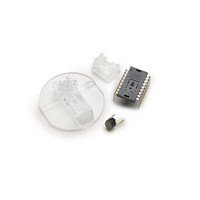
OPT SENS BUNDLE W/A-6030 RL CLIP
Manufacturer
Avago Technologies US Inc.
Specifications of ADNB-6031-EV
Description/function
Laser Mouse Bundle
Interface Type
SPI
Product
Display Modules
Touch Panel
No Touch Panel
For Use With/related Products
ADNS-6030
Lead Free Status / RoHS Status
Lead free / RoHS Compliant
Lead Free Status / RoHS Status
Lead free / RoHS Compliant, Lead free / RoHS Compliant


7
LASER Drive Mode
The laser is driven in pulsed mode during normal
operation. A calibration mode is provided which drives
the laser in continuous (CW) operation.
Eye Safety
The ADNS-6030 and the associated components in
the schematic of Figure 5 are intended to comply
with Class 1 Eye Safety Requirements of IEC 60825-
1. Avago Technologies suggests that manufacturers
perform testing to verify eye safety on each mouse.
It is also recommended to review possible single
fault mechanisms beyond those described below in
the section “Single Fault Detection”. Under normal
conditions, the ADNS-6030 generates the drive current
for the laser diode (ADNV-6340).
In order to stay below the Class 1 power requirements,
LASER_CTRL0 (register 0x1a), LASER_CTRL1 (register
0x1f ), LSRPWR_CFG0 (register 0x1c) and LSRPWR_CFG1
(register 0x1d) must be programmed to appropriate
values. The system comprised of the ADNS-6030 and
ADNV-6340, is designed to maintain the output beam
power within Class 1 requirements over components
manufacturing tolerances and the recommended
temperature range when adjusted per the procedure
below and implemented as shown in the recommended
application circuit of Figure 5. For more information,
please refer to Avago Technologies Laser Mouse Sensor
Eye Safety Application Note AN 5230.
LASER Power Adjustment Procedure
1. The ambient temperature should be 25C
2. Set V
3. Set the Range bit (bit 7 of register 0x1a) to 0.
4. Set the Range_C complement bit (bit 7 of register
5. Set the Match_bit (bit 5 of register 0x1a) to the cor-
6. Set the Match_C_bit (bit 5 of register 0x1f ) to the
7. Enable the Calibration mode by writing to bits
8. Write the Calibration mode complement bits to reg-
9. Set the laser current to the minimum value by writ-
10. Program registers 0x1c and 0x1d with increas-
11. If it was not possible to achieve the power target,
12. Set the Range and Range_C bits in registers 0x1a
13. Program registers 0x1c and 0x1d with increas-
14. Save the value of registers 0x1a, 0x1c, 0x1d, and
15. Reset the mouse, reload the register values from
Good engineering practices such as regular power meter
calibration, random quality assurance retest of calibrated
mice, etc. should be used to guarantee performance,
0x1f ) to 1.
rect value for the bin designation of the laser being
used.
complement of the Match_bit.
[3,2,1] of register 0x1A so the laser will be driven
with 100% duty cycle.
ister 0x1f.
ing 0x00 to register 0x1c, and the complementary
value 0xFF to register 0x1d.
ing values to achieve an output power as close
to 506uW as possible without exceeding it. If this
power is obtained, the calibration is complete, skip
to step 14.
set the laser current to the minimum value by writ-
ing 0x00 to register 0x1c, and the complementary
value 0xff to register 0x1d.
and 0x1f, respectively, to choose to the higher laser
current range.
ing values to achieve an output power as close to
506uW as possible without exceeding it.
0x1f in non-volatile memory in the mouse. These
registers must be restored to these values every
time the ADNS-6030 is reset.
non-volatile memory, enable Calibration mode, and
measure the laser power to verify that the calibra-
tion is correct.
DD
to its permanent value.
±
5C.
Related parts for ADNB-6031-EV
Image
Part Number
Description
Manufacturer
Datasheet
Request
R

Part Number:
Description:
OPTICAL MOUSE EVALUATION KIT
Manufacturer:
Avago Technologies US Inc.
Datasheet:

Part Number:
Description:
Display Modules & Development Tools Bundle w/Trim Lens
Manufacturer:
Avago Technologies US Inc.

Part Number:
Description:
Display Modules & Development Tools Bundle w/Trim Lens
Manufacturer:
Avago Technologies US Inc.

Part Number:
Description:
Display Modules & Development Tools Mouse sensor
Manufacturer:
Avago Technologies US Inc.
Part Number:
Description:
Display Modules & Development Tools Mouse sensor
Manufacturer:
Avago Technologies US Inc.

Part Number:
Description:
Display Modules & Development Tools Bundle w/Trim Lens
Manufacturer:
Avago Technologies US Inc.

Part Number:
Description:
Display Modules & Development Tools Sensor+Round Lens
Manufacturer:
Avago Technologies US Inc.
Part Number:
Description:
Display Modules & Development Tools Mouse sensor
Manufacturer:
Avago Technologies US Inc.

Part Number:
Description:
Display Modules & Development Tools Mouse sensor
Manufacturer:
Avago Technologies US Inc.

Part Number:
Description:
Display Modules & Development Tools Bundle w/Trim Lens
Manufacturer:
Avago Technologies US Inc.

Part Number:
Description:
OPTOCOUPLER GATE DRV 2A 16-SOIC
Manufacturer:
Avago Technologies US Inc.
Datasheet:
Part Number:
Description:
OPTOCOUPLER 2CH 2.5A 16-SOIC
Manufacturer:
Avago Technologies US Inc.
Datasheet:

Part Number:
Description:
OPTOCOUPLER GATE DRV 0.4A 16SOIC
Manufacturer:
Avago Technologies US Inc.
Datasheet:

Part Number:
Description:
OPTOCOUPLER 2.0A 250KHZ 8-DIP
Manufacturer:
Avago Technologies US Inc.
Datasheet:

Part Number:
Description:
OPTOCOUPLER 2.0A 250KHZ GW 8-SMD
Manufacturer:
Avago Technologies US Inc.
Datasheet: