FLUKE-287/FVF Fluke Electronics, FLUKE-287/FVF Datasheet - Page 46
FLUKE-287/FVF
Manufacturer Part Number
FLUKE-287/FVF
Description
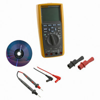
COMBO KIT DMM & ACCESSORY
Manufacturer
Fluke Electronics
Series
FlukeView® Forms, 28xr
Type
Digital (DMM)r
Specifications of FLUKE-287/FVF
Includes
Battery, Case, Clips, Software, Test Leads
Style
Handheld
Display Digits
4.5
Display Type
LCD, Bar Graph
Display Count
50000
Function
Voltage, Current, Resistance, Capacitance, Temperature, Frequency
Functions, Extra
Continuity, dB
Features
Backlight, Data Logging, Hold, Memory, Min/Max/Ave
Ranging
Auto/Manual
Response
True RMS
Lead Free Status / RoHS Status
Lead free / RoHS Compliant
Other names
287/FVF
3340186
614-1151
3340186
614-1151


287/289
Users Manual
To measure capacitance, position the rotary switch to P and set
up the Meter as shown in Figure 19. If the display doesn’t
already indicate the Meter is measuring capacitance, press the
softkey labeled Menu. Next, move the menu selector to the
menu item labeled Diode,Cap and press the softkey labeled
Cap.
Testing Diodes
Use the diode test to check diodes, transistors, silicon controlled
rectifiers (SCRs), and other semiconductor devices. The test
36
To improve measurement accuracy of small value
capacitors, press Menu and move the menu selector
to the menu item labeled REL. With the test leads
open, press the softkey labeled REL to subtract the
residual capacitance of the Meter and leads.
To avoid possible damage to the meter or to the
equipment under test, disconnect circuit power
and discharge all high-voltage capacitors before
testing diodes.
W Caution
Note
sends a current through a semiconductor junction, and then
measures the junction’s voltage drop. A typical junction drops
0.5 V to 0.8 V.
To test a diode out of a circuit, position the rotary switch to P
and set up the meter as shown in Figure 20. If the display
doesn’t already indicate the Meter is in the Diode Test function,
press the softkey labeled Menu. Next, move the menu selector
to the menu item labeled Diode,Cap and press the softkey
labeled Diode.
If the beeper is enabled during diode test, it will beep briefly for a
normal junction and sound continuously for a shorted junction,
below 0.1 V. See the “Disabling and Enabling the Beeper”
section to disable the beeper.
In a circuit, a similar diode should still indicate a forward-bias
reading of 0.5 V to 0.8 V; however, the reading can vary
depending on the resistance of other pathways between the
probe tips.
R and MIN MAX are disabled when the Meter is
setup for diode test.
Note