FLUKE-287/FVF Fluke Electronics, FLUKE-287/FVF Datasheet - Page 55
FLUKE-287/FVF
Manufacturer Part Number
FLUKE-287/FVF
Description
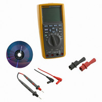
COMBO KIT DMM & ACCESSORY
Manufacturer
Fluke Electronics
Series
FlukeView® Forms, 28xr
Type
Digital (DMM)r
Specifications of FLUKE-287/FVF
Includes
Battery, Case, Clips, Software, Test Leads
Style
Handheld
Display Digits
4.5
Display Type
LCD, Bar Graph
Display Count
50000
Function
Voltage, Current, Resistance, Capacitance, Temperature, Frequency
Functions, Extra
Continuity, dB
Features
Backlight, Data Logging, Hold, Memory, Min/Max/Ave
Ranging
Auto/Manual
Response
True RMS
Lead Free Status / RoHS Status
Lead free / RoHS Compliant
Other names
287/FVF
3340186
614-1151
3340186
614-1151


To measure duty cycle, position the rotary switch on one of the
functions allowing frequency measurements shown in Figure 23.
Press the softkey labeled Menu and move the menu selector to
the menu item labeled Hz,%,ms. Next press the softkey labeled
%.
As shown in Figure 26, the duty cycle percentage is shown in the
primary display while the signal frequency appears in the
secondary display. The mini-measurement display indicates the
0
Menu
8:10pm
Figure 26. Duty Cycle Display
100
49.75
Save
59.756
200
123.45 VAC
300
400
%
Hz
Duty Cycle
06/13/07
Auto Range
Setup
500 VAC
est24.eps
volts or amps value of the input signal. The bar graph tracks the
volts or amps value of the signal and not the duty cycle value.
The pulse polarity is displayed to the right of the duty cycle value.
J indicates a positive pulse and K indicates a negative pulse.
To change the polarity being measured, press the softkey
labeled J K. The polarity indicator changes to the opposite
polarity.
For 5 V logic signals, use the 5 V dc range. For 12 V switching
signals in automobiles, use the 50 V dc range. For sine waves,
use the lowest ac or dc range that does not result in multiple
triggering. A manually-selected lower input range will often
measure better than the AUTO-selected input range.
Measuring Pulse Width
The pulse width function measures the amount of time a signal is
high or low, as shown in Figure 27. The measured waveform
must be
The meter measures pulse width from 0.025 ms to 1250.0 ms
ranges.
To measure pulse width, position the rotary switch to one of the
functions allowing frequency measurements shown in Figure 23.
Press the softkey labeled Menu and move the menu selector to
the menu item labeled Hz,%,ms. Next, press the softkey labeled
ms.
periodic;
its pattern must repeat at equal time intervals.
Making Measurements
45