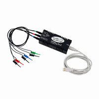
28014 Parallax Inc, 28014 Datasheet - Page 43

28014
Manufacturer Part Number
28014
Description
OSCILLOSCOPE USB 200KHZ
Manufacturer
Parallax Inc
Type
USBr
Specifications of 28014
Includes
Probes, Software, USB Cable
Bandwidth
200kHz
Channels
Dual
Display Type
None - Requires Computer and Monitor
Probe Type
Hook Probes x1 (3)
Sampling Rate (per Second)
500ks/s
Voltage - Input, Max
20V p-p
Voltage - Supply
5 VDC, USB Powered
Product
Microcontroller Accessories
Lead Free Status / RoHS Status
Lead free / RoHS Compliant
Features
-
Input Impedance
-
Rise Time (typ)
-
Lead Free Status / Rohs Status
Lead free / RoHS Compliant
Other names
Q2119020
Chapter #3: Sine Waves
SINE WAVES WITH THE BASIC STAMP FREQOUT COMMAND
A sine wave is a common electrical signal that can be viewed on the OPTAscope. Unlike
digital signals that typically are either high or low, analog signals can be high, low, or
any value in between. One of the most common types of sine waves that we can sense is
the sound wave. Sound waves permeate the air in three dimensions in the same manner
that ripples flow across a pond in two dimensions. A cross-section of the surface of this
pond would look something like the waveform in Figure 3-1.
Despite the fact that BASIC Stamps are digital by their nature, they can generate sine
waves. The interesting thing here is how they generate sine waves. The BASIC Stamp
must approximate the sine wave with a sequence of digital square waves that is later
filtered into a nice, clean sine wave. When you connect a piezoelectric speaker to a sine
wave you will hear a tone (provided the sine wave is oscillating at a frequency within the
audible range). This may sound confusing, but it will clear up as we work through the
next lesson. First, we need a little more background information.
The pulse train used to control servos is only one type of signal in a family of signals
called PWM. PWM stands for pulse width modulation. The servo pulse train is unique
in that it has a fixed “off-time”. Most PWM signals have variable off-time as well as
variable on-time. Consider the pulse train depicted in Figure 3-2.
Figure 3-1:
Typical sine wave – one cycle.
Figure 3-2:
PWM signal
train


