28014 Parallax Inc, 28014 Datasheet - Page 5
28014
Manufacturer Part Number
28014
Description
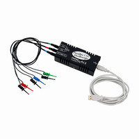
OSCILLOSCOPE USB 200KHZ
Manufacturer
Parallax Inc
Type
USBr
Specifications of 28014
Includes
Probes, Software, USB Cable
Bandwidth
200kHz
Channels
Dual
Display Type
None - Requires Computer and Monitor
Probe Type
Hook Probes x1 (3)
Sampling Rate (per Second)
500ks/s
Voltage - Input, Max
20V p-p
Voltage - Supply
5 VDC, USB Powered
Product
Microcontroller Accessories
Lead Free Status / RoHS Status
Lead free / RoHS Compliant
Features
-
Input Impedance
-
Rise Time (typ)
-
Lead Free Status / Rohs Status
Lead free / RoHS Compliant
Other names
Q2119020


Preface........................................................................................................................iii
Chapter #1: Oscilloscope Basics..............................................................................1
Chapter #2: Servo Pulse Square Waves ................................................................23
Chapter #3: Sine Waves...........................................................................................35
Copyright and Reproduction .......................................................................................... iv
Foreign Translations ...................................................................................................... iv
Special Contributors ...................................................................................................... iv
What is an Oscilloscope? ...............................................................................................1
How Does an Oscilloscope Work? .................................................................................2
Running the OPTAscope 81M for the First Time............................................................5
Activity #1: Viewing High and Low Signals ...................................................................14
Activity #2: Using the Horizontal Dial and Edge Triggering ..........................................18
Summary ......................................................................................................................21
Exercises ......................................................................................................................21
Further Investigation .....................................................................................................21
Pulse Width Modulation and Hobby Servos .................................................................23
Activity #1: Measuring Pulses for Servo Control...........................................................25
Activity #2: Measuring Time Varying Servo Pulse Widths ............................................31
Summary ......................................................................................................................33
Exercises ......................................................................................................................33
Further Investigation .....................................................................................................33
Sine Waves with the BASIC Stamp FREQOUT Command..........................................35
Activity #1: Sine Wave Triggering.................................................................................36
Activity #2: Sine Wave Frequency and Amplitude Measurement .................................41
Activity #3: Dual Sine Wave Measurement...................................................................43
Summary ......................................................................................................................46
Exercises ......................................................................................................................47
Further Investigation .....................................................................................................48
Plot Area ....................................................................................................................6
Horizontal and Vertical Dials, Channel and Run/Stop Buttons ..................................7
Plot Area Indicator......................................................................................................9
Display Screen .........................................................................................................10
Files / Settings Tab ..................................................................................................10
Trigger Tab...............................................................................................................11
Cursors Tab .............................................................................................................12
Measurements Tab ..................................................................................................13
Table of Contents