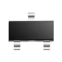
BAT54S /T3 NXP Semiconductors, BAT54S /T3 Datasheet - Page 3

BAT54S /T3
Manufacturer Part Number
BAT54S /T3
Description
Schottky (Diodes & Rectifiers) DIODE SCHTKY TAPE-11
Manufacturer
NXP Semiconductors
Datasheet
1.BAT54S235.pdf
(7 pages)
Specifications of BAT54S /T3
Product
Schottky Diodes
Peak Reverse Voltage
30 V
Forward Continuous Current
0.2 A
Max Surge Current
0.6 A
Configuration
Dual Series
Recovery Time
5 ns
Forward Voltage Drop
0.8 V @ 0.1 A
Maximum Reverse Leakage Current
2 uA @ 25 V
Operating Temperature Range
+ 125 C
Mounting Style
SMD/SMT
Package / Case
TO-236AB
Lead Free Status / RoHS Status
Lead free / RoHS Compliant
Other names
BAT54S,235
NXP Semiconductors
LIMITING VALUES
In accordance with the Absolute Maximum Rating System (IEC 60134).
THERMAL CHARACTERISTICS
Note
1. Refer to SOT23 standard mounting conditions.
CHARACTERISTICS
T
2002 Mar 04
Per diode
V
I
I
I
T
T
Per device
P
R
Per diode
V
I
t
C
amb
F
FRM
FSM
R
rr
SYMBOL
SYMBOL
SYMBOL
stg
j
R
tot
F
Schottky barrier (double) diodes
th j-a
d
= 25 °C unless otherwise specified.
continuous reverse voltage
continuous forward current
repetitive peak forward current
non-repetitive peak forward current
storage temperature
junction temperature
total power dissipation
thermal resistance from junction to
ambient
forward voltage
reverse current
reverse recovery time
diode capacitance
PARAMETER
PARAMETER
PARAMETER
t
t
T
note 1
see Fig.3
V
when switched from I
to I
measured at I
see Fig.6
f = 1 MHz; V
3
p
p
amb
R
≤ 1 s; δ ≤ 0.5
< 10 ms
I
I
I
I
I
F
F
F
F
F
R
= 25 V; see Fig.4
= 0.1 mA
= 1 mA
= 10 mA
= 30 mA
= 100 mA
= 10 mA; R
≤ 25 °C
CONDITIONS
CONDITIONS
CONDITIONS
R
R
= 1 V; see Fig.5
= 1 mA;
L
= 100 Ω;
F
= 10 mA
−
−
−
−
−65
−
−
240
320
400
500
800
2
5
10
MIN.
VALUE
MAX.
BAT54 series
500
Product data sheet
30
200
300
600
+150
125
230
MAX.
mV
mV
mV
mV
mV
μA
ns
pF
UNIT
UNIT
K/W
V
mA
mA
mA
°C
°C
mW
UNIT


