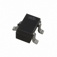
BAT54W,115 NXP Semiconductors, BAT54W,115 Datasheet - Page 3

BAT54W,115
Manufacturer Part Number
BAT54W,115
Description
DIODE SCHOTTKY 30V 200MA SOT323
Manufacturer
NXP Semiconductors
Datasheet
1.BAT54CW115.pdf
(5 pages)
Specifications of BAT54W,115
Package / Case
SC-70-3, SOT-323-3
Voltage - Forward (vf) (max) @ If
800mV @ 100mA
Voltage - Dc Reverse (vr) (max)
30V
Current - Average Rectified (io)
200mA (DC)
Current - Reverse Leakage @ Vr
2µA @ 25V
Diode Type
Schottky
Speed
Small Signal =< 200mA (Io), Any Speed
Reverse Recovery Time (trr)
5ns
Capacitance @ Vr, F
10pF @ 1V, 1MHz
Mounting Type
Surface Mount
Product
Schottky Diodes
Peak Reverse Voltage
30 V
Forward Continuous Current
0.2 A
Max Surge Current
0.6 A
Configuration
Single
Recovery Time
5 ns
Forward Voltage Drop
0.8 V @ 0.1 A
Maximum Reverse Leakage Current
2 uA @ 25 V
Operating Temperature Range
+ 125 C
Mounting Style
SMD/SMT
Rectifier Type
Schottky Diode
Peak Rep Rev Volt
30V
Avg. Forward Curr (max)
0.2
Rev Curr
2uA
Peak Non-repetitive Surge Current (max)
0.6A
Forward Voltage
0.8@0.1AV
Operating Temp Range
-65C to 125C
Package Type
SC-70
Rev Recov Time
5ns
Operating Temperature Classification
Military
Mounting
Surface Mount
Pin Count
3
Lead Free Status / RoHS Status
Lead free / RoHS Compliant
Lead Free Status / RoHS Status
Lead free / RoHS Compliant, Lead free / RoHS Compliant
Other names
568-3416-2
934028880115
BAT54W T/R
934028880115
BAT54W T/R
Available stocks
Company
Part Number
Manufacturer
Quantity
Price
Part Number:
BAT54W,115
Manufacturer:
NEXPERIA/安世
Quantity:
20 000
Philips Semiconductors
LIMITING VALUES
In accordance with the Absolute Maximum Rating System (IEC 134).
ELECTRICAL CHARACTERISTICS
T
Note
1. Pulsed test: t
THERMAL CHARACTERISTICS
Note
1. Refer to SOT323 standard mounting conditions.
1996 Mar 19
Per diode
V
I
I
I
P
T
T
T
Per diode
V
I
t
C
R
SYMBOL
SYMBOL
SYMBOL
F
FRM
FSM
amb
R
rr
stg
j
amb
R
tot
F
d
th j-a
Schottky barrier (double) diodes
= 25 C unless otherwise specified.
continuous reverse voltage
continuous forward current
repetitive peak forward current
non-repetitive peak forward current
total power dissipation (per package)
storage temperature
junction temperature
operating ambient temperature
forward voltage
reverse current
reverse recovery time
diode capacitance
thermal resistance from junction to ambient
p
= 300 s; = 0.02.
PARAMETER
PARAMETER
PARAMETER
t
t
T
see Fig.6
V
when switched from I
I
I
f = 1 MHz; V
p
p
R
R
amb
R
I
I
I
I
I
= 10 mA; R
= 1 mA: see Fig.9
F
F
F
F
F
= 25 V; note 1; see Fig.7
1 s;
10 ms
= 0.1 mA
= 1 mA
= 10 mA
= 30 mA
= 100 mA
note 1
3
25 C
CONDITIONS
CONDITIONS
0.5
R
L
= 1 V; see Fig.8
CONDITIONS
= 100 ; measured at
F
= 10 mA to
240
320
400
500
800
2
5
10
BAT54W series
MIN.
65
65
VALUE
MAX.
625
Product specification
30
200
300
600
200
+150
125
+125
MAX.
mV
mV
mV
mV
mV
ns
pF
A
UNIT
UNIT
K/W
V
mA
mA
mA
mW
C
C
C
UNIT


