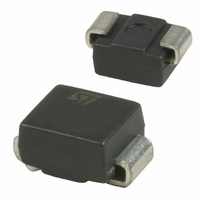
STTH2R02U STMicroelectronics, STTH2R02U Datasheet - Page 3

STTH2R02U
Manufacturer Part Number
STTH2R02U
Description
DIODE ULTRA FAST 200V 2A SMB
Manufacturer
STMicroelectronics
Datasheet
1.STTH2R02QRL.pdf
(9 pages)
Specifications of STTH2R02U
Voltage - Forward (vf) (max) @ If
1V @ 2A
Voltage - Dc Reverse (vr) (max)
200V
Current - Average Rectified (io)
2A
Current - Reverse Leakage @ Vr
3µA @ 200V
Diode Type
Standard
Speed
Fast Recovery =< 500ns, > 200mA (Io)
Reverse Recovery Time (trr)
30ns
Mounting Type
Surface Mount
Package / Case
DO-214AA, SMB
Product
Ultra Fast Recovery Rectifier
Configuration
Single
Reverse Voltage
200 V
Forward Voltage Drop
1.2 V at 6 A
Recovery Time
30 ns
Forward Continuous Current
2 A
Max Surge Current
75 A
Reverse Current Ir
3 uA
Mounting Style
SMD/SMT
Maximum Operating Temperature
+ 175 C
Minimum Operating Temperature
- 65 C
Lead Free Status / RoHS Status
Lead free / RoHS Compliant
Capacitance @ Vr, F
-
Lead Free Status / Rohs Status
Lead free / RoHS Compliant
Other names
497-5256-2
Available stocks
Company
Part Number
Manufacturer
Quantity
Price
Company:
Part Number:
STTH2R02U
Manufacturer:
STM
Quantity:
466
Part Number:
STTH2R02U
Manufacturer:
ST
Quantity:
20 000
Company:
Part Number:
STTH2R02UY
Manufacturer:
ST
Quantity:
50 000
STTH2R02
Table 4.
Figure 1.
Figure 3.
Symbol
V
I
RM
t
t
FP
rr
fr
50
40
30
20
10
100
0
80
60
40
20
0
0.0
0.0
Reverse recovery time
Reverse recovery current
Forward recovery time
Forward recovery voltage
0.1
P = 5 W
P = 5 W
Dynamic characteristics
Peak current versus duty cycle
Forward voltage drop versus
forward current (maximum values)
0.5
0.2
P = 2 W
P = 2 W
0.3
Parameter
1.0
P = 1 W
P = 1 W
0.4
T
j
=150°C
0.5
1.5
0.6
T
j
=25°C
0.7
I
I
M
M
δ
d
=tp/T
=tp/T
2.0
0.8
T
T
V
0.9
FM
I
V
I
V
I
V
I
V
I
T
δ
F
F
F
F
F
(V)
j
tp
tp
R
R
R
FR
= 1 A, dI
= 1 A, dI
= 2 A, dI
= 2 A, dI
= 2 A, dI
= 25° C
= 30 V, T
= 30 V, T
= 160 V, T
1.0
2.5
= 1.1 x V
Test conditions
F
F
F
F
F
Figure 2.
Figure 4.
/dt = -50 A/µs,
/dt = -100 A/µs,
/dt = -200 A/µs,
/dt = 100 A/µs
/dt = 100 A/µs,
j
j
= 25° C
= 25° C
Fmax
j
= 125° C
50
40
30
20
10
1.0
0.9
0.8
0.7
0.6
0.5
0.4
0.3
0.2
0.1
0.0
0
1.E-02
, T
0.0
j
Single pulse
= 25° C
S
cu
SMA
=1cm²
Forward voltage drop versus
forward current (typical values)
Relative variation of thermal
impedance junction to case versus
pulse duration (SMA)
1.E-01
0.5
T
j
=150°C
1.E+00
1.0
Min.
T
j
=25°C
1.E+01
1.5
Typ
2.0
23
15
40
3
Characteristics
1.E+02
2.0
Max.
30
20
4
t
V
P
(s)
FM
(V)
1.E+03
2.5
Unit
ns
ns
A
V
3/9


