D4BL-3CRB-A Omron, D4BL-3CRB-A Datasheet - Page 10
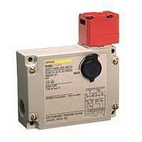
D4BL-3CRB-A
Manufacturer Part Number
D4BL-3CRB-A
Description
Contact OSTI For Purchase
Manufacturer
Omron
Series
D4BLr
Specifications of D4BL-3CRB-A
Contact Configuration
DPST-1NC / 1NO + SPST-NC
Contact Voltage Ac Max
250V
Contact Current Ac Max
10A
Switch Operation
ON
Switch Terminals
Screw
Contact Current Max
10A
Lead Free Status / RoHS Status
na
Lead Free Status / RoHS Status
na


■ Circuit Connection Example
• Terminals 11 and 32 are connected internally and so connect terminals 12 and 31 for safety-circuit input. (GS-ET-19).
• When using indicators, connect them to the auxiliary circuit side (monitor circuit) or the solenoid input terminals as shown below.
• The indicators can be used to confirm the open/closed status of the door, the ON/OFF status of the power supply, and the ON/OFF status of the
• Do not connect the indicators in parallel with the direct opening contact. If the indicators are broken, a short-circuit current may flow, causing
• The 24-VDC solenoid terminals have polarity. Confirm the polarity before wiring.
• Be sure to use a special pushbutton switch to stop and start machinery and release locks.
1. Orange: Lights when the solenoid turns ON.
3. Orange: Lights when the solenoid turns ON.
solenoid.
equipment to malfunction.
Green: Lights when the door opens.
Green: Lights when door closes.
11
23
11
21
Auxiliary circuit
(monitor circuit)
Auxiliary circuit
(monitor circuit)
12
22
12
24
http://www.ia.omron.com/
31
31
Safety circuit
Safety circuit
(Power supply side)
(Power supply side)
32
32
(Ground side)
(Ground side)
LED (orange)
LED (green)
LED (orange)
LED (green)
Solenoid
Solenoid
E1 (+)
E2 (−)
E1 (+)
E2 (−)
2. Orange: Lights when the solenoid turns ON.
4. Orange: Lights when the solenoid turns ON.
Green: Lights when power turns ON.
Green: Lights when power turns ON.
11
23
11
21
(c)Copyright OMRON Corporation 2007 All Rights Reserved.
Auxiliary circuit
(monitor circuit)
Auxiliary circuit
(monitor circuit)
12
24
12
22
31
31
Safety circuit
Safety circuit
(Power supply side)
(Power supply side)
32
32
(Ground side)
(Ground side)
LED (orange)
LED (green)
LED (orange)
LED (green)
Solenoid
Solenoid
E1 (+)
E2 (−)
E1 (+)
E2 (−)
D4BL
10
Related parts for D4BL-3CRB-A
Image
Part Number
Description
Manufacturer
Datasheet
Request
R

Part Number:
Description:
Contact OSTI For Purchase
Manufacturer:
Omron
Datasheet:

Part Number:
Description:
Safety Switch
Manufacturer:
Omron
Datasheet:
Part Number:
Description:
Locking Solenoid Safety Switch
Manufacturer:
Omron
Datasheet:
Part Number:
Description:
Interlock Switch
Manufacturer:
Omron
Datasheet:
Part Number:
Description:
G1/2,1NC/1NO,mch Lck,110v Rel.
Manufacturer:
Omron
Datasheet:
Part Number:
Description:
Solenoid Interlock Switch
Manufacturer:
Omron
Datasheet:
Part Number:
Description:
Solenoid Interlock Switch
Manufacturer:
Omron
Datasheet:
Part Number:
Description:
SOLENOID INTERLOCK SWITCH
Manufacturer:
Omron
Datasheet:
Part Number:
Description:
Contact OSTI For Purchase
Manufacturer:
Omron
Datasheet:
Part Number:
Description:
LIMIT SWITCH ADJ ROLL LEVER
Manufacturer:
Omron
Datasheet: