D4BL-3CRB-A Omron, D4BL-3CRB-A Datasheet - Page 12
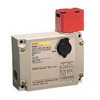
D4BL-3CRB-A
Manufacturer Part Number
D4BL-3CRB-A
Description
Contact OSTI For Purchase
Manufacturer
Omron
Series
D4BLr
Specifications of D4BL-3CRB-A
Contact Configuration
DPST-1NC / 1NO + SPST-NC
Contact Voltage Ac Max
250V
Contact Current Ac Max
10A
Switch Operation
ON
Switch Terminals
Screw
Contact Current Max
10A
Lead Free Status / RoHS Status
na
Lead Free Status / RoHS Status
na


G9SA-301 (24 VAC/VDC) + D4BL-@G-@ (Solenoid Lock Type) Circuit Diagram (Auto-reset)
Lock signal
Operation signal
Guard Lock Safety-door Switch S2
OPEN
Timing Chart
Limit switch S1
Operation signal
Lock signal
K1 and K2
(NC)
K1 and K2
(NO)
KM1 and KM2
(NC)
KM1 and KM2
(NO)
32
31
12
11
http://www.ia.omron.com/
A1 A2 T11
TH
SA
S2
PE T21
12
11
a
K1
T12
K1
6
b
K2
T23 T22
K2
S1
1
a
b
T31
Control
A
Circuit
Guard opens
Note: 1. This example circuit is for Category 4.
B
K1
K2
T32
Feedback loop
2. The lock can be released at any time. Therefore, do not use a model
3
4
KM1
KM2
2
5
with a solenoid lock in applications where the operator may be
exposed to danger when the guard opens. Use a model with a
mechanical lock.
13
14 24 34 42
KM1 KM2
23 33 41
S1:
S2:
KM1 and KM2: Magnetic Contactor
M:
Operation
instruction
JP
KM1
KM2
1
2
3
4
5
6
Motor controller
Safety Limit Switch
with direct opening mechanism
(D4B-N, D4N, D4F)
Guard Lock Safety-door Switch
3-phase motor
(c)Copyright OMRON Corporation 2007 All Rights Reserved.
M
D4BL
12
Related parts for D4BL-3CRB-A
Image
Part Number
Description
Manufacturer
Datasheet
Request
R

Part Number:
Description:
Contact OSTI For Purchase
Manufacturer:
Omron
Datasheet:

Part Number:
Description:
Safety Switch
Manufacturer:
Omron
Datasheet:
Part Number:
Description:
Locking Solenoid Safety Switch
Manufacturer:
Omron
Datasheet:
Part Number:
Description:
Interlock Switch
Manufacturer:
Omron
Datasheet:
Part Number:
Description:
G1/2,1NC/1NO,mch Lck,110v Rel.
Manufacturer:
Omron
Datasheet:
Part Number:
Description:
Solenoid Interlock Switch
Manufacturer:
Omron
Datasheet:
Part Number:
Description:
Solenoid Interlock Switch
Manufacturer:
Omron
Datasheet:
Part Number:
Description:
SOLENOID INTERLOCK SWITCH
Manufacturer:
Omron
Datasheet:
Part Number:
Description:
Contact OSTI For Purchase
Manufacturer:
Omron
Datasheet:
Part Number:
Description:
LIMIT SWITCH ADJ ROLL LEVER
Manufacturer:
Omron
Datasheet: