D4BL-3CRB-A Omron, D4BL-3CRB-A Datasheet - Page 20
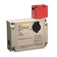
D4BL-3CRB-A
Manufacturer Part Number
D4BL-3CRB-A
Description
Contact OSTI For Purchase
Manufacturer
Omron
Series
D4BLr
Specifications of D4BL-3CRB-A
Contact Configuration
DPST-1NC / 1NO + SPST-NC
Contact Voltage Ac Max
250V
Contact Current Ac Max
10A
Switch Operation
ON
Switch Terminals
Screw
Contact Current Max
10A
Lead Free Status / RoHS Status
na
Lead Free Status / RoHS Status
na


• To protect the Switch from damage due to short-circuits, be sure to
Contact Protection Circuits
Using a contact protection circuit to increase the contact durability, prevent noise, and suppress the generation of carbide or nitric acid. Be sure to
apply the contact protection circuit correctly, otherwise adverse results may occur.
The following tables shows typical examples of contact protection circuits. If the Switch is used in an excessively humid location for switching a load
that easily generates arcs, such as an inductive load, the arcs may generate NOx, which will change into HNO
Consequently, the internal metal parts may corrode and the Switch may fail. Be sure to select the best contact protection circuit from the following
table.
Typical Examples of Contact Protection Circuits
Do not use the following types of contact protection circuit.
CR
Diode
Diode + Zener
diode
Varistor
connect in series a quick-response fuse with a breaking current 1.5
to 2 times larger than the rated current to the Switch. When
complying with EN certified ratings, use a 10-A IEC 60269-
compliant gI or gG fuse.
Power
supply
C
Circuit example
Load
This circuit arrangement is very
effective for diminishing arcing at
the contacts when breaking the
circuit. However, since electrical
energy is stored in C (capacitor)
when the contacts are open, the
current from C flows into the
contacts when they close. This
may lead to contact welding.
Power
supply
Power
supply
Power
supply
Power
supply
http://www.ia.omron.com/
Power
supply
C
C
R
R
Inductive
load
Inductive
load
Inductive
load
Inductive
Inductive
load
load
*See
remarks.
Yes
No
No
Yes
Applicable
AC
current
Yes
Yes
Yes
Yes
Yes
DC
Power
supply
*Load impedance must be much smaller than the
CR circuit impedance when using the Switch for an
AC voltage.
The operating time of the contacts will be
increased if the load is a Relay or solenoid.
Connecting the CR circuit in parallel to the
load is effective when the power supply
voltage is 24 or 48 V and in parallel to the
contacts when the power supply voltage is
100 to 200 V.
The energy stored in the coil reaches the coil
as current via the diode connected in
parallel, and is dissipated as Joule heat by
the resistance of the inductive load. This
type of circuit increases the release time
more than the CR type.
This circuit effectively shortens the reset
time in applications where the release time
of a diode circuit is too slow.
This circuit prevents a high voltage from
being applied across the contacts by using
the constant-voltage characteristic of a
varistor. This circuit also somewhat
increases the reset time. Connecting the
varistor across the load is effective when the
supply voltage is 24 to 48 V, and across the
contacts when the supply voltage is 100 to
240 V.
C
Load
This circuit arrangement is very
useful for diminishing arcing at the
contacts when breaking the circuit.
However, since the charging current
to C flows into the contacts when
they are closed, contact welding
may occur.
Features and remarks
(c)Copyright OMRON Corporation 2007 All Rights Reserved.
Although it is thought that switching a DC
inductive load is more difficult than a resistive
load, an appropriate contact protection circuit
can achieve almost the same characteristics.
Use the following as guides for C and R
values:
C: 1 to 0.5 μ F per 1 A of contact current (A)
R: 0.5 to 1 Ω per 1 V of contact voltage (V)
These values depend on various factors,
including the load
optimum values experimentally.
Capacitor C suppresses the discharge when
the contacts are opened, while the resistor R
limits the current applied when the contacts
are closed the next time.
Generally, use a capacitor with a low
dielectric strength of 200 to 300 V. For
applications in an AC circuit, use an AC
capacitor (with no polarity).
Use a diode having a reverse breakdown voltage of
more than 10 times the circuit voltage, and a
forward current rating greater than the load current.
Use a Zener diode with a low breakdown
voltage.
---
3
when it reacts with moisture.
Element selection
characteristics
. Confirm
C-5
Related parts for D4BL-3CRB-A
Image
Part Number
Description
Manufacturer
Datasheet
Request
R

Part Number:
Description:
Contact OSTI For Purchase
Manufacturer:
Omron
Datasheet:

Part Number:
Description:
Safety Switch
Manufacturer:
Omron
Datasheet:
Part Number:
Description:
Locking Solenoid Safety Switch
Manufacturer:
Omron
Datasheet:
Part Number:
Description:
Interlock Switch
Manufacturer:
Omron
Datasheet:
Part Number:
Description:
G1/2,1NC/1NO,mch Lck,110v Rel.
Manufacturer:
Omron
Datasheet:
Part Number:
Description:
Solenoid Interlock Switch
Manufacturer:
Omron
Datasheet:
Part Number:
Description:
Solenoid Interlock Switch
Manufacturer:
Omron
Datasheet:
Part Number:
Description:
SOLENOID INTERLOCK SWITCH
Manufacturer:
Omron
Datasheet:
Part Number:
Description:
Contact OSTI For Purchase
Manufacturer:
Omron
Datasheet:
Part Number:
Description:
LIMIT SWITCH ADJ ROLL LEVER
Manufacturer:
Omron
Datasheet: