STPS140U STMicroelectronics, STPS140U Datasheet - Page 3
STPS140U
Manufacturer Part Number
STPS140U
Description
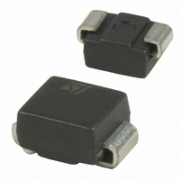
DIODE SCHOTTKY 40V 1A SMB
Manufacturer
STMicroelectronics
Datasheet
1.STPS140A.pdf
(7 pages)
Specifications of STPS140U
Voltage - Forward (vf) (max) @ If
550mV @ 1A
Voltage - Dc Reverse (vr) (max)
40V
Current - Average Rectified (io)
1A
Current - Reverse Leakage @ Vr
12µA @ 40V
Diode Type
Schottky
Speed
Fast Recovery =< 500ns, > 200mA (Io)
Mounting Type
Surface Mount
Package / Case
DO-214AA, SMB
Product
Schottky Rectifiers
Peak Reverse Voltage
40 V
Forward Continuous Current
1 A
Max Surge Current
60 A
Configuration
Single
Forward Voltage Drop
0.65 V at 2 A
Maximum Reverse Leakage Current
12 uA
Operating Temperature Range
+ 150 C
Mounting Style
SMD/SMT
Rectifier Type
Schottky Diode
Peak Rep Rev Volt
40V
Avg. Forward Curr (max)
1A
Rev Curr
12uA
Peak Non-repetitive Surge Current (max)
60A
Forward Voltage
0.65V
Operating Temp Range
-65C to 150C
Package Type
SMB
Operating Temperature Classification
Military
Mounting
Surface Mount
Pin Count
2
Lead Free Status / RoHS Status
Lead free / RoHS Compliant
Reverse Recovery Time (trr)
-
Capacitance @ Vr, F
-
Lead Free Status / Rohs Status
Lead free / RoHS Compliant
Other names
497-2490-2
Available stocks
Company
Part Number
Manufacturer
Quantity
Price
Company:

Part Number:
STPS140U
Manufacturer:
ST
Quantity:
50 000
Part Number:
STPS140U
Manufacturer:
ST
Quantity:
20 000


Figure 5: Non repetitive surge peak forward
current versus overload duration (maximum
values) (SMA)
Figure
impedance junction to ambient versus pulse
duration
e(Cu)=35µm, recommended pad layout) (SMA)
Figure 9: Reverse leakage current versus
reverse voltage applied (typical values)
8
7
6
5
4
3
0
1.0
0.9
0.8
0.7
0.6
0.5
0.4
0.3
0.0
1E+3
1E+2
1E+0
2
0.2
1
0.1
1E+1
1E-2
1E-1
1E-3
1E-2
I (A)
M
Z
I
I (µA)
0
M
th(j-c)
δ = 0.5
Single pulse
δ = 0.2
δ = 0.1
R
δ
/R
7:
=0.5
t
5
th(j-c)
(epoxy
1E-1
Relative
10
1E-2
15
printed
t(s)
t (s)
1E+0
p
V (V)
T =125°C
T =25°C
variation
T =75°C
j
j
j
R
20
1E-1
25
circuit
1E+1
of
δ
30
=tp/T
T
thermal
T =100°C
35
T =25°C
T =50°C
a
board,
a
a
tp
1E+0
1E+2
40
Figure 6: Non repetitive surge peak forward
current versus overload duration (maximum
values) (SMB)
Figure
impedance junction to ambient versus pulse
duration
e(Cu)=35µm, recommended pad layout) (SMB)
Figure
reverse voltage applied (typical values)
8
7
6
5
4
3
2
0
200
100
1.0
0.9
0.8
0.7
0.6
0.5
0.4
0.3
0.2
0.1
0.0
1
50
20
10
1E-3
1E-2
I (A)
M
1
C(pF)
Z
I
th(j-c)
δ = 0.5
Single pulse
M
δ = 0.2
δ = 0.1
/R
δ
8:
10:
=0.5
t
th(j-c)
1E-1
2
(epoxy
Relative
Junction
1E-2
1E+0
5
printed
t(s)
t (s)
V (V)
p
variation
R
capacitance
1E+1
10
1E-1
circuit
of
δ
20
=tp/T
1E+2
STPS140
T
thermal
F=1MHz
T =25°C
T =100°C
versus
T =25°C
board,
j
T =50°C
a
a
a
tp
1E+3
1E+0
3/7
50
Related parts for STPS140U
Image
Part Number
Description
Manufacturer
Datasheet
Request
R

Part Number:
Description:
STMicroelectronics [RIPPLE-CARRY BINARY COUNTER/DIVIDERS]
Manufacturer:
STMicroelectronics
Datasheet:
Part Number:
Description:
STMicroelectronics [LIQUID-CRYSTAL DISPLAY DRIVERS]
Manufacturer:
STMicroelectronics
Datasheet:

Part Number:
Description:
BOARD EVAL FOR MEMS SENSORS
Manufacturer:
STMicroelectronics
Datasheet:
Part Number:
Description:
NPN TRANSISTOR POWER MODULE
Manufacturer:
STMicroelectronics
Datasheet:
Part Number:
Description:
TURBOSWITCH ULTRA-FAST HIGH VOLTAGE DIODE
Manufacturer:
STMicroelectronics
Datasheet:
Part Number:
Description:
Manufacturer:
STMicroelectronics
Datasheet:
Part Number:
Description:
DIODE / SCR MODULE
Manufacturer:
STMicroelectronics
Datasheet:
Part Number:
Description:
DIODE / SCR MODULE
Manufacturer:
STMicroelectronics
Datasheet:
Part Number:
Description:
Search -----> STE16N100
Manufacturer:
STMicroelectronics
Datasheet:
Part Number:
Description:
Search ---> STE53NA50
Manufacturer:
STMicroelectronics
Datasheet:
Part Number:
Description:
NPN Transistor Power Module
Manufacturer:
STMicroelectronics
Datasheet:
Part Number:
Description:
DIODE / SCR MODULE
Manufacturer:
STMicroelectronics
Datasheet: