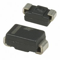
STTH112A STMicroelectronics, STTH112A Datasheet - Page 3

STTH112A
Manufacturer Part Number
STTH112A
Description
DIODE ULT FAST 1A 1200V SMA
Manufacturer
STMicroelectronics
Datasheet
1.STTH112A.pdf
(8 pages)
Specifications of STTH112A
Voltage - Forward (vf) (max) @ If
1.9V @ 1A
Voltage - Dc Reverse (vr) (max)
1200V (1.2kV)
Current - Average Rectified (io)
1A
Current - Reverse Leakage @ Vr
5µA @ 1200V
Diode Type
Standard
Speed
Fast Recovery =< 500ns, > 200mA (Io)
Reverse Recovery Time (trr)
75ns
Mounting Type
Surface Mount
Package / Case
DO-214AC, SMA
Product
Ultra Fast Recovery Rectifier
Configuration
Single
Reverse Voltage
1200 V
Forward Voltage Drop
1.9 V
Recovery Time
75 ns
Forward Continuous Current
1 A
Max Surge Current
18 A
Reverse Current Ir
5 uA
Mounting Style
SMD/SMT
Maximum Operating Temperature
+ 175 C
Minimum Operating Temperature
- 50 C
Lead Free Status / RoHS Status
Lead free / RoHS Compliant
Capacitance @ Vr, F
-
Lead Free Status / Rohs Status
Lead free / RoHS Compliant
Other names
497-8048-2
STTH112A
STTH112A
Available stocks
Company
Part Number
Manufacturer
Quantity
Price
Company:
Part Number:
STTH112A
Manufacturer:
STMicroelectronics
Quantity:
77 980
Part Number:
STTH112A
Manufacturer:
ST
Quantity:
20 000
STTH112
Figure 1.
Figure 3.
Figure 5.
2.2
2.0
1.8
1.6
1.4
1.2
1.0
0.8
0.6
0.4
0.2
0.0
1.0
0.9
0.8
0.7
0.6
0.5
0.4
0.3
0.2
0.1
0.0
1.0
0.9
0.8
0.7
0.6
0.5
0.4
0.3
0.2
0.1
0.0
1.E-01
1.E-01
0.0
P(W)
Z
Z
δ = 0.5
δ = 0.5
Single pulse
Single pulse
th(j-c)
δ = 0.2
δ = 0.1
th(j-c)
δ = 0.2
δ = 0.1
epoxy FR4, L
0.1
/R
/R
0.2
th(j-c)
th(j-c)
Conduction losses versus average
current
Relative variation of thermal
impedance junction ambient versus
pulse duration (DO-41)
Relative variation of thermal
impedance junction ambient versus
pulse duration (epoxy FR4)(SMB)
1.E+00
1.E+00
leads
0.3
= 10mm
δ = 0.05
0.4
0.5
δ = 0.1
I
F(AV)
1.E+01
1.E+01
t (s)
t (s)
p
p
0.6
(A)
δ = 0.2
0.7
0.8
1.E+02
1.E+02
δ = 0.5
0.9
δ
δ
δ
=tp/T
=tp/T
=tp/T
1.0
T
T
δ = 1
T
Doc ID 9343 Rev 5
1.1
tp
tp
tp
1.E+03
1.E+03
1.2
Figure 2.
Figure 4.
Figure 6.
100.0
1.0
0.9
0.8
0.7
0.6
0.5
0.4
0.3
0.2
0.1
0.0
110
100
10.0
90
80
70
60
50
40
30
20
10
1.E-01
1.0
0.1
0
0
Z
R
0.0
δ = 0.5
δ = 0.2
Single pulse
th(j-c)
δ = 0.1
I
th(j-a)
FM
(A)
1
0.5
/R
(°C/W)
(typical values)
th(j-c)
T =125°C
Forward voltage drop versus
forward current
Relative variation of thermal
impedance junction ambient versus
pulse duration (epoxy FR4) (SMA)
Thermal resistance junction to
ambient versus copper surface
under each lead (DO-41, SMB)
j
2
1.E+00
1.0
epoxy printed circuit board FR4, copper thickness: 35µm
3
1.5
(maximum values)
T =125°C
j
2.0
4
SMB
1.E+01
S(cm²)
t (s)
V
Electrical characteristics
p
FM
2.5
5
(V)
(maximum values)
T =25°C
3.0
6
j
L
leads
DO-41
=10mm
1.E+02
3.5
7
δ
=tp/T
4.0
8
T
4.5
9
tp
1.E+03
5.0
10
3/8


