STGB10NC60KT4 STMicroelectronics, STGB10NC60KT4 Datasheet - Page 4
STGB10NC60KT4
Manufacturer Part Number
STGB10NC60KT4
Description
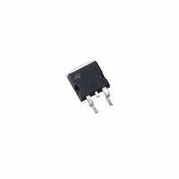
IGBT N-CHAN 600V 10A D2PAK
Manufacturer
STMicroelectronics
Series
PowerMESH™r
Datasheet
1.STGB10NC60KT4.pdf
(11 pages)
Specifications of STGB10NC60KT4
Voltage - Collector Emitter Breakdown (max)
600V
Vce(on) (max) @ Vge, Ic
2.5V @ 15V, 5A
Current - Collector (ic) (max)
20A
Power - Max
60W
Input Type
Standard
Mounting Type
Surface Mount
Package / Case
D²Pak, TO-263 (2 leads + tab)
Lead Free Status / RoHS Status
Lead free / RoHS Compliant
Igbt Type
-
Other names
497-5737-2
Available stocks
Company
Part Number
Manufacturer
Quantity
Price
Company:

Part Number:
STGB10NC60KT4
Manufacturer:
ST
Quantity:
12 500


Electrical characteristics
2.1
4/11
Figure 2.
Figure 4.
Table 7.
1. Eon is the tun-on losses when a typical diode is used in the test circuit in figure 2. If the IGBT is offered in a
2. Turn-off losses include also the tail of the collector current
Electrical characteristics (curves)
Output characteristics
Transconductance
Symbol
E
E
E
E
package with a co-pak diode, the co-pack diode is used as external diode. IGBTs & Diode are at the same
temperature (25°C and 125°C)
E
E
on
off
on
off
ts
ts
(1)
(2)
(1)
(2)
Turn-on switching losses
Turn-off switching losses
Total switching losses
Turn-on switching losses
Turn-off switching losses
Total switching losses
Switching energy (inductive load)
Parameter
Doc ID 11842 Rev 4
V
R
(see Figure 18)
V
R
Tj= 125°C
(see Figure 18)
CC
CC
G
G
= 10Ω, V
= 10Ω, V
Figure 3.
Figure 5.
= 390V, I
= 390V, I
Test conditions
GE
GE
C
C
=15V,
= 15V,
= 5A
= 5A
Transfer characteristics
Collector-emitter on voltage vs
temperature
Min
Typ
140
162
249
55
85
87
STGB10NC60K
Max Unit
µJ
µJ
µJ
µJ
µJ
µJ
Related parts for STGB10NC60KT4
Image
Part Number
Description
Manufacturer
Datasheet
Request
R

Part Number:
Description:
STMicroelectronics [RIPPLE-CARRY BINARY COUNTER/DIVIDERS]
Manufacturer:
STMicroelectronics
Datasheet:
Part Number:
Description:
STMicroelectronics [LIQUID-CRYSTAL DISPLAY DRIVERS]
Manufacturer:
STMicroelectronics
Datasheet:

Part Number:
Description:
BOARD EVAL FOR MEMS SENSORS
Manufacturer:
STMicroelectronics
Datasheet:
Part Number:
Description:
NPN TRANSISTOR POWER MODULE
Manufacturer:
STMicroelectronics
Datasheet:
Part Number:
Description:
TURBOSWITCH ULTRA-FAST HIGH VOLTAGE DIODE
Manufacturer:
STMicroelectronics
Datasheet:
Part Number:
Description:
Manufacturer:
STMicroelectronics
Datasheet:
Part Number:
Description:
DIODE / SCR MODULE
Manufacturer:
STMicroelectronics
Datasheet:
Part Number:
Description:
DIODE / SCR MODULE
Manufacturer:
STMicroelectronics
Datasheet:
Part Number:
Description:
Search -----> STE16N100
Manufacturer:
STMicroelectronics
Datasheet:
Part Number:
Description:
Search ---> STE53NA50
Manufacturer:
STMicroelectronics
Datasheet:
Part Number:
Description:
NPN Transistor Power Module
Manufacturer:
STMicroelectronics
Datasheet:
Part Number:
Description:
DIODE / SCR MODULE
Manufacturer:
STMicroelectronics
Datasheet: