STGB35N35LZT4 STMicroelectronics, STGB35N35LZT4 Datasheet
STGB35N35LZT4
Specifications of STGB35N35LZT4
Available stocks


Related parts for STGB35N35LZT4


STGB35N35LZT4 Summary of contents
Page 1
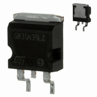
... Zener diodes between gate-collector and gate- emitter provide overvoltage protection capabilities. The device also exhibits low on-state voltage drop and low threshold drive for use in automotive ignition system. Table 1. Device summary Order codes STGB35N35LZ-1 STGB35N35LZT4 STGP35N35LZ June 2010 E 450 mJ, 345 V, internally clamped IGBT AS TAB D²PAK Figure 1. ...
Page 2
Contents Contents 1 Electrical ratings . . . . . . . . . . . . . . . . . . . . . . . . . . . . . . . . . . . ...
Page 3
STGB35N35LZ, STGP35N35LZ 1 Electrical ratings Table 2. Absolute maximum ratings Symbol V Collector-emitter voltage (V CES V Emitter collector voltage (V ECS (1) I Continuous collector current (1) I Continuous collector current (2) I ...
Page 4
Electrical characteristics 2 Electrical characteristics (T =25 °C unless otherwise specified) j Table 4. Static Symbol Collector emitter V clamped voltage CES(clamped Emitter collector break- V (BR)ECS down voltage (V Gate emitter clamped V GE(clamped) voltage Collector cut-off ...
Page 5
STGB35N35LZ, STGP35N35LZ Table 6. Functional characteristics Symbol Functional test open U.I.S. secondary coil Table 7. Switching time Symbol Resistive load t Turn-on delay time d(on) t Rise time r Resistive load t Turn-on delay time d(on) t Rise time r ...
Page 6
Electrical characteristics 2.1 Electrical characteristics (curves) Figure 2. Collector-emitter saturation voltage vs temperature V 1.4 CE(sat 1.3 1.2 1.1 1 0.9 -50 - Figure 4. Output characteristics ( ...
Page 7
STGB35N35LZ, STGP35N35LZ Figure 6. Output characteristics ( ( Figure 8. Collector cut-off current vs temperature 100 I (µA) CES ...
Page 8
Electrical characteristics Figure 10. Normalized gate threshold voltage vs temperature 1.2 V GE(th) (norm) 1.1 1.0 0.9 0.8 0.7 0.6 0.5 -50 - Figure 12. Thermal impedance 8/17 Figure 11. Gate charge 6 V (V) GE ...
Page 9
STGB35N35LZ, STGP35N35LZ 3 Test circuits Figure 13. Test circuit for inductive load switching Figure 15. Switching waveform Td(off) Td(on) Tr(Ion) Ton Figure 14. Gate charge test circuit AM01504v1 90% 10% 90% 10% Tr(Voff) Tcross ...
Page 10
Package mechanical data 4 Package mechanical data In order to meet environmental requirements, ST offers these devices in different grades of ® ECOPACK packages, depending on their level of environmental compliance. ECOPACK specifications, grade definitions and product status are available ...
Page 11
STGB35N35LZ, STGP35N35LZ Table 8. D²PAK mechanical data Dim Min. Typ. 4.40 0.03 0.70 1.14 0.45 1.23 8.95 7.50 10 8.50 ...
Page 12
Package mechanical data Figure 16. D²PAK mechanical data drawing 0079457_O 12/17 STGB35N35LZ, STGP35N35LZ Doc ID 12253 Rev 5 ...
Page 13
STGB35N35LZ, STGP35N35LZ Dim I²PAK (TO-262) mechanical data mm Min Typ Max 4.40 4.60 2.40 2.72 0.61 0.88 1.14 1.70 0.49 0.70 1.23 1.32 8.95 9.35 2.40 2.70 ...
Page 14
Package mechanical data 14/17 TO-220 type A mechanical data Dim Min A 4.40 b 0.61 b1 1.14 c 0.48 D 15. 2.40 e1 4.95 F 1.23 H1 6. 3.50 L20 L30 ...
Page 15
STGB35N35LZ, STGP35N35LZ 5 Packaging mechanical data 2 D PAK FOOTPRINT TAPE MECHANICAL DATA mm DIM. MIN. MAX. A0 10.5 10.7 B0 15.7 15.9 D 1.5 1.6 D1 1.59 1.61 E 1.65 1.85 F 11.4 11.6 K0 4.8 5.0 P0 3.9 ...
Page 16
Revision history 6 Revision history Table 9. Document revision history Date 29-Mar-2006 03-Jun-2009 05-Nov-2009 16-Feb-2010 03-Jun-2010 16/17 Revision 1 Initial release. 2 Document status promoted from preliminary data to datasheet. Chapter 2.1: Electrical characteristics (curves) 3 Inserted 4 Added new ...
Page 17
... STGB35N35LZ, STGP35N35LZ Information in this document is provided solely in connection with ST products. STMicroelectronics NV and its subsidiaries (“ST”) reserve the right to make changes, corrections, modifications or improvements, to this document, and the products and services described herein at any time, without notice. All ST products are sold pursuant to ST’s terms and conditions of sale. ...