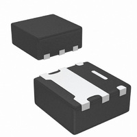
SIB911DK-T1-GE3 Vishay, SIB911DK-T1-GE3 Datasheet - Page 5

SIB911DK-T1-GE3
Manufacturer Part Number
SIB911DK-T1-GE3
Description
MOSFET DL P-CH 20V PPAK SC75-6
Manufacturer
Vishay
Datasheet
1.SIB911DK-T1-GE3.pdf
(7 pages)
Specifications of SIB911DK-T1-GE3
Transistor Polarity
P-Channel
Fet Type
2 P-Channel (Dual)
Fet Feature
Standard
Rds On (max) @ Id, Vgs
295 mOhm @ 1.5A, 4.5V
Drain To Source Voltage (vdss)
20V
Current - Continuous Drain (id) @ 25° C
1.5A
Vgs(th) (max) @ Id
1V @ 250µA
Gate Charge (qg) @ Vgs
4nC @ 8V
Input Capacitance (ciss) @ Vds
115pF @ 10V
Power - Max
1.1W
Mounting Type
Surface Mount
Package / Case
PowerPAK® SC-75-6L Dual
Minimum Operating Temperature
- 55 C
Configuration
Dual
Resistance Drain-source Rds (on)
0.295 Ohm @ 4.5 V
Forward Transconductance Gfs (max / Min)
3 S
Drain-source Breakdown Voltage
20 V
Gate-source Breakdown Voltage
+/- 8 V
Continuous Drain Current
1.5 A
Power Dissipation
1100 mW
Maximum Operating Temperature
+ 150 C
Mounting Style
SMD/SMT
Continuous Drain Current Id
-2.6A
Drain Source Voltage Vds
-20V
On Resistance Rds(on)
560mohm
Rds(on) Test Voltage Vgs
8V
Threshold Voltage Vgs Typ
-1V
Lead Free Status / RoHS Status
Lead free / RoHS Compliant
Lead Free Status / RoHS Status
Lead free / RoHS Compliant, Lead free / RoHS Compliant
Other names
SIB911DK-T1-GE3TR
TYPICAL CHARACTERISTICS 25 °C, unless otherwise noted
* The power dissipation P
dissipation limit for cases where additional heatsinking is used. It is used to determine the current rating, when this rating falls below the package
limit.
Document Number: 74475
S-80515-Rev. B, 10-Mar-08
3.0
2.5
2.0
1.5
1.0
0.5
0.0
0
25
D
T
C
is based on T
Current Derating*
50
- Case Temperature (°C)
75
J(max)
100
= 150 °C, using junction-to-case thermal resistance, and is more useful in settling the upper
125
New Product
150
4
3
2
1
0
25
50
T
C
- Case Temperature (°C)
Power Derating
75
Vishay Siliconix
100
SiB911DK
www.vishay.com
125
150
5


