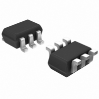
SI1539DL-T1-E3 Vishay, SI1539DL-T1-E3 Datasheet - Page 10

SI1539DL-T1-E3
Manufacturer Part Number
SI1539DL-T1-E3
Description
MOSFET N/P-CH 30V SC70-6
Manufacturer
Vishay
Series
TrenchFET®r
Datasheets
1.SI1539DL-T1-E3.pdf
(8 pages)
2.SI1539DL-T1-E3.pdf
(8 pages)
3.SI1539DL-T1-E3.pdf
(12 pages)
Specifications of SI1539DL-T1-E3
Transistor Polarity
N and P-Channel
Fet Type
N and P-Channel
Fet Feature
Logic Level Gate
Rds On (max) @ Id, Vgs
480 mOhm @ 590mA, 10V
Drain To Source Voltage (vdss)
30V
Current - Continuous Drain (id) @ 25° C
540mA, 420mA
Vgs(th) (max) @ Id
1V @ 250µA
Gate Charge (qg) @ Vgs
1.4nC @ 10V
Power - Max
270mW
Mounting Type
Surface Mount
Package / Case
SC-70-6, SC-88, SOT-363
Minimum Operating Temperature
- 55 C
Configuration
Dual
Resistance Drain-source Rds (on)
0.48 Ohm @ 10 V @ N Channel
Drain-source Breakdown Voltage
30 V
Gate-source Breakdown Voltage
+/- 20 V
Continuous Drain Current
0.54 A @ N Channel or 0.42 A @ P Channel
Power Dissipation
270 mW
Maximum Operating Temperature
+ 150 C
Mounting Style
SMD/SMT
Continuous Drain Current Id
630mA
Drain Source Voltage Vds
30V
On Resistance Rds(on)
480mohm
Rds(on) Test Voltage Vgs
10V
Threshold Voltage Vgs Typ
1V
Module Configuration
Dual
Rohs Compliant
Yes
Lead Free Status / RoHS Status
Lead free / RoHS Compliant
Lead Free Status / RoHS Status
Lead free / RoHS Compliant, Lead free / RoHS Compliant
Other names
SI1539DL-T1-E3TR
Available stocks
Company
Part Number
Manufacturer
Quantity
Price
Part Number:
SI1539DL-T1-E3
Manufacturer:
VISHAY/威世
Quantity:
20 000
AN814
Vishay Siliconix
NOTE: Although they are intended for low-power applications,
devices in the 6-pin SC-70 will handle power dissipation in
excess of 0.2 W.
Testing
To aid comparison further, Figure 2 illustrates the dual-channel
SC-70 thermal performance on two different board sizes and
two different pad patterns. The results display the thermal
performance out to steady state. The measured steady state
values of Rθ
www.vishay.com
2
SC-70 (6-PIN)
LITTLE FOOT SC-70 (6-PIN)
1) Minimum recommended pad pattern (see
Figure 2) on the EVB of 0.5 inches x
0.6 inches.
2) Industry standard 1” square PCB with
maximum copper both sides.
Room Ambient 25 _C
P
P
P
D
D
D
+
+ 150
+ 312 mW
T
JA
J(max)
400
for the dual 6-pin SC-70 are as follows:
Rq
o
C * 25
o
JA
* T
C W
A
o
C
Elevated Ambient 60 _C
P
P
P
D
D
D
+
+ 150
+ 225 mW
T
518_C/W
413_C/W
J(max)
400
Rq
o
C * 60
o
JA
* T
C W
A
o
C
The results show that if the board area can be increased and
maximum copper traces are added, the thermal resistance
reduction is limited to 20%. This fact confirms that the power
dissipation is restricted with the package size and the Alloy 42
leadframe.
ASSOCIATED DOCUMENT
Single-Channel LITTLE FOOT SC-70 6-Pin MOSFET Copper
Leadframe Version, REcommended Pad Pattern and Thermal
Performance, AN815, (http://www.vishay.com/doc?71334).
FIGURE 2.
500
400
300
200
100
0
10
-5
10
-4
Comparison of Dual SC70-6 on EVB and 1”
Square FR4 PCB.
10
-3
10
-2
Time (Secs)
Dual EVB
10
-1
1” Square FR4 PCB
1
Document Number: 71237
10
100
12-Dec-03
1000


