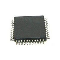
STA304 STMicroelectronics, STA304 Datasheet - Page 6

STA304
Manufacturer Part Number
STA304
Description
Audio DSPs Digital Audio Proc
Manufacturer
STMicroelectronics
Datasheet
1.STA304.pdf
(31 pages)
Specifications of STA304
Mounting Style
SMD/SMT
Package / Case
TQFP-44
Lead Free Status / RoHS Status
Lead free / RoHS Compliant
Available stocks
Company
Part Number
Manufacturer
Quantity
Price
Company:
Part Number:
STA304-5C/
Manufacturer:
MIC
Quantity:
1 526
Part Number:
STA304A
Manufacturer:
SANKEN
Quantity:
20 000
Company:
Part Number:
STA304A/
Manufacturer:
pericom
Quantity:
11 120
STA304
DC ELECTRICAL CHARACTERISTICS
2.0 AC’97 BANK REGISTER OVERVIEW
The AC `97 interface is compliant to ‘Audio Codec `97 – Revision 2.1’ specification, as far as the protocol used.
All the registers described in this specification, including Standard, Vendor Reserved and Extended Audio (AC
`97 2.0) registers, are available in this device, but just relevant registers which are described in paragraph 11
(Register Summary) are implemented.
The ATE mode feature has been implemented for test purpose: for related details refer to the ‘Audio Codec `97
– Revision 2.1’ specification.
2.1 Reading AC `97 Registers
Since the AC`97 register bank has been implemented as a contiguous RAM space (from a DSP point of view)
the content of the RAM itself will be returned as the result of a read operation. This should be followed as a
general rule of thumb but, where not possible, a different approach has been used. Hereby is a list of the reg-
isters, and bits, that do not follow this rule or that have a particular handling:
•
•
6/31
Note 1: Takes into account 200mV voltage drop in both supply lines
Note 2: X is the source/sinc current under worst case conditions and is reflected in the name of the I/O cell according to the drive capability.
Note 1: Min condition: V
DIGITAL CHARACTERISTICS-SPDIF RECEIVER (RXP,RXN pins only, SPDIF - MODE = ANALOG)
Symbol
VHY
VTH
T
CodecID_0, CodecID_1:
These two bit are respectively bits 14 and 15 of registers 28h (Extended Audio ID) and 3Ch (EWxtended
Modem ID). When a read operation of these registers is performed the returned value is based on the status
of the SA pin: CodecID_0 report the status of SA pin, CodecID_1 always report 0. Other bits of these regis-
ters return the related RAM register contents. Also note that the status of the SA pin is not readable by the
DSP.
PR4:
The bit 12 of register 26h (Powerdown, ctrl/start) is used to set the AC`97 BIT_CLK and SDATA_IN signal
to a low state. In response to a Warmers the status of this bit is set back to its default 0 value. In response
R
ZIN
V
V
V
I
T
V
pu
CK
oh
pu
ol
ih
R
il
Low Level Input Voltage
High Level Input Voltage
Low Level Output Voltage
High Level Output Voltage
Pull-up current
Equivalent Pull-up resistance
Reset Active Time
Master Clock Period
Input Resistance
Dufferential Input Voltage
Input Hysteresis
dd
Parameter
= 3.0V, 125°C Min process; Max. condition: V
Iol = X mA
V
V
i
DD
= 0V;
= 3.3V
Test Condition
dd
= 3.6 V, -20°C max process.
0.8*V
0.85*V
Min.
-25
200
DD
DD
----------------- -
49.152
2·T
Typ.
-66
50
50
1
CK
0.2*V
0.4*V
Max.
-125
DD
DD
Unit
KΩ
mV
mV
kΩ
µA
ns
ns
V
V
V
V
Note
1,2
1,2
1


