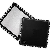
LAN88710BM_samples SMSC, LAN88710BM_samples Datasheet - Page 37

LAN88710BM_samples
Manufacturer Part Number
LAN88710BM_samples
Description
Ethernet ICs MII/RMII 10/100 Automot Transceiver
Manufacturer
SMSC
Datasheet
1.LAN88710BM_SAMPLES.pdf
(80 pages)
Specifications of LAN88710BM_samples
Ethernet Connection Type
10BASE-T, 100BASE-TX
Minimum Operating Temperature
- 40 C
Mounting Style
SMD/SMT
Product
Ethernet Transceivers
Standard Supported
IEEE802.3, IEEE802.3u
Supply Voltage (max)
3.6 V
Supply Voltage (min)
1.6 V
Maximum Operating Temperature
+ 105 C
Package / Case
QFN-32
Lead Free Status / RoHS Status
Lead free / RoHS Compliant
Small Footprint MII/RMII 10/100 Ethernet Transceiver for Automotive Applications
Datasheet
SMSC LAN88710AM/LAN88710BM
3.7
3.7.1
Configuration straps allow various features of the device to be automatically configured to user defined
values. Configuration straps are latched upon Power-On Reset (POR) and pin reset (nRST).
Configuration straps include internal resistors in order to prevent the signal from floating when
unconnected. If a particular configuration strap is connected to a load, an external pull-up or pull-down
resistor should be used to augment the internal resistor to ensure that it reaches the required voltage
level prior to latching. The internal resistor can also be overridden by the addition of an external
resistor.
Note: The system designer must guarantee that configuration strap pins meet the timing
Note: When externally pulling configuration straps high, the strap should be tied to VDDIO, except
PHYAD[2:0]: PHY Address Configuration
The PHYAD[2:0] configuration straps are driven high or low to give each PHY a unique address. This
address is latched into an internal register at the end of a hardware reset (default = 000b). In a multi-
transceiver application (such as a repeater), the controller is able to manage each transceiver via the
unique address. Each transceiver checks each management data frame for a matching address in the
relevant bits. When a match is recognized, the transceiver responds to that particular frame. The PHY
address is also used to seed the scrambler. In a multi-transceiver application, this ensures that the
scramblers are out of synchronization and disperses the electromagnetic radiation across the
frequency spectrum.
The device’s SMI address may be configured using hardware configuration to any value between 0
and 7. The user can configure the PHY address using Software Configuration if an address greater
than 7 is required. The PHY address can be written (after SMI communication at some address is
established) using the
straps are multiplexed with other signals as shown in
Configuration Straps
requirements specified in
page
the device may capture incorrect strap values.
for REGOFF and nINTSEL which should be tied to VDD2A.
72. If configuration strap pins are not at the correct voltage level prior to being latched,
ADDRESS BIT
Table 3.5 Pin Names for Address Bits
PHYAD
PHYAD[0]
PHYAD[1]
PHYAD[2]
bits of the
Section 5.6.3, "Power-On nRST & Configuration Strap Timing," on
DATASHEET
RXER/RXD4/PHYAD0
37
Special Modes
RXCLK/PHYAD1
RXD3/PHYAD2
PIN NAME
Table
3.5.
Register. The PHYAD[2:0] configuration
Revision 1.1 (05-26-10)


