PAXCDC10 Red Lion Controls, PAXCDC10 Datasheet - Page 18
PAXCDC10
Manufacturer Part Number
PAXCDC10
Description
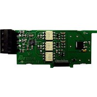
RS485 Serial Communications Output Interface Card With Terminal Block
Manufacturer
Red Lion Controls
Specifications of PAXCDC10
Accessory Type
RS485 Serial Communications Output Interface Card With Terminal Block
Brand/series
PAX Series
Card Type
RS485 Serial Communications Output Card
Data Rate
7⁄8 Bits
Standards
cULus Listed, CSA Certified and CE Marked
Voltage, Working
50 V
Pax Label Kit
189 Different Engineering Units, Labels Inserted Inside the Unit
For Use With
Red Lion PAX Digital Input Panel Meters
Lead Free Status / RoHS Status
Lead free / RoHS Compliant


frequency, Rate assignment should be set to
shown with an annunciator of ‘
actually
B select
updates for the Rate display. Values of 0.1 and 0.2 seconds will update the
display correctly but may cause the display to appear unsteady. The factory
setting of 1.0 will update the display every second minimum.
display is forced to zero. (For more explanation, refer to Input Frequency
Calculation.) The High Update Time must be higher than the Low Update Time
and higher than the desired slowest readable speed (one divided by pulses per
second). The factory setting of 2.0, will force the display to zero for speeds
below 0.5 Hz or a pulse every 2 seconds.
rate displays and any setpoint value assigned to these displays. This parameter
does not affect rate scaling calculations.
Scaling function. Each linear segment has two scaling points which define the
upper and lower endpoints of the segment. The number of segments used
depends on the linearity of the process and the display accuracy required as
described below.
Linear Application – 2 Scaling Points
Rate display from 0 up to the maximum input frequency. For typical zero based
frequency measurements (0 Hz = 0 on display), leave
For non-zero based 2 scaling point applications, set
zero segment (
PAXI: RATE ASSIGNMENT
PAXI: LINEARIZER SEGMENTS
6.4 MODULE 4 - R
Module 4 is the programming for the Rate parameters. For maximum input
, the remaining related parameters are not accessible. The Rate value is
Note: For PAXR,
For measuring the rate (speed) of pulses on Input A, select
The Low Update Time is the minimum amount of time between display
The High Update Time is the maximum amount of time before the Rate
This selects the decimal point position for Rate, Minimum and Maximum
This parameter specifies the number of linear segments used for the Rate
Linear processes use a single segment (two scaling points) to provide a linear
LOW UPDATE TIME (DISPLAY UPDATE) *
HIGH UPDATE TIME (DISPLAY ZERO) *
. This assignment is independent of the counting modes.
on the unit’s display.
RATE DECIMAL POSITION
&
is actually
to
to
to
’ in the Display Mode.
) and segment 1 (
seconds
seconds
on the unit’s display and
when not in use. When set to
ATE
&
, to enter both the
(factory setting).
I
PARAMETER MENU
NPUT
. For Input
).
is
P
18
ARAMETERS
Non-linear Application – Up to 10 Scaling Points
provide a piece-wise linear approximation representing the non-linear function.
The Rate display will be linear throughout each individual segment (i.e.
between sequential scaling points). Thus, the greater the number of segments,
the greater the conformity accuracy. Several linearization equations are
available in the software.
About Scaling Points
Rate Display Value (
Scaling points are entered sequentially in ascending order of Rate Input Value.
endpoints of the first linear segment. Setting
the first scaling point to 0.0 for typical single segment, zero based applications.
When multiple segments are used, the upper scaling point for a given segment
becomes the lower scaling point for the next sequential segment. Thus, for each
additional segment used, only one additional scaling point must be programmed.
mnemonics, and the Factory Default Settings for each point.
is automatically set to 0 and does not appear when
Note: For all linear and most non-linear applications, the Scaling Point 1
the arrow keys.
*
PAXI: RATE DISPLAY VALUE FOR SCALING POINT 1
PAXI: RATE INPUT VALUE FOR SCALING POINT 1
SEGMENT
Factory Setting can be used without affecting basic start-up.
Non-linear processes may utilize up to nine segments (ten scaling points) to
Each Scaling Point is specified by two programmable parameters: A desired
Two scaling points must be programmed to define the upper and lower
The following chart shows the Scaling Points, the corresponding Parameter
Confirm the Rate Display Value for the first Scaling Point is 0. This parameter
Confirm the Rate Input Value for the first Scaling Point is 0.0. (See Note)
parameters (
Consult the factory before using any non-zero values for Scaling Point 1. These
parameters are automatically set to 0 and do not appear when
Enter the desired Rate Display Value for the second Scaling Point by using
1
2
3
4
5
6
7
8
9
RATE DISPLAY VALUE FOR SCALING POINT 2
SCALING
POINT
10
1
2
3
4
5
6
7
8
9
and
PARAMETER
(
DISPLAY
) and a corresponding Rate Input Value (
to
to
to
) should be set to 0 and 0.0 respectively.
DEFAULT
DISPLAY
000000
001000
002000
003000
004000
005000
006000
007000
008000
009000
)
-
PAXR & I
PARAMETER
, automatically factory sets
INPUT
. (See Note)
DEFAULT
00000.0
01000.0
02000.0
03000.0
04000.0
05000.0
06000.0
07000.0
08000.0
09000.0
INPUT
.
).
Related parts for PAXCDC10
Image
Part Number
Description
Manufacturer
Datasheet
Request
R

Part Number:
Description:
Counter
Manufacturer:
Red Lion Controls
Datasheet:
Part Number:
Description:
Miniature Length Sensor
Manufacturer:
Red Lion Controls
Datasheet:
Part Number:
Description:
Model Lsc - Single Channel Output Length Sensor
Manufacturer:
Red Lion Controls
Datasheet: