PAXCDC10 Red Lion Controls, PAXCDC10 Datasheet - Page 26
PAXCDC10
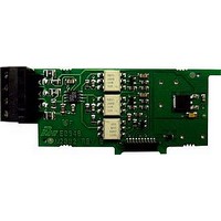
Manufacturer Part Number
PAXCDC10
Description
RS485 Serial Communications Output Interface Card With Terminal Block
Manufacturer
Red Lion Controls
Specifications of PAXCDC10
Accessory Type
RS485 Serial Communications Output Interface Card With Terminal Block
Brand/series
PAX Series
Card Type
RS485 Serial Communications Output Card
Data Rate
7⁄8 Bits
Standards
cULus Listed, CSA Certified and CE Marked
Voltage, Working
50 V
Pax Label Kit
189 Different Engineering Units, Labels Inserted Inside the Unit
For Use With
Red Lion PAX Digital Input Panel Meters
Lead Free Status / RoHS Status
Lead free / RoHS Compliant


Auto/Manual Mode Register (MMR) ID: U
meter controls the setpoint and analog output. In Manual Mode (1) the outputs
are defined by the registers SOR and AOR. When transferring from auto mode
to manual mode, the meter holds the last output value (until the register is
changed by a write). Each output may be independently changed to auto or
manual. In a write command string (VU), any character besides 0 or 1 in a field
will not change the corresponding output mode.
Analog Output Register (AOR) ID: W
of values of this register is 0 to 4095, which corresponds to the analog output
range per the following chart:
Numeric Transmissions
processes it as a Numeric transmission. In this case, only the recognized numbers
and punctuation are displayed. All other characters in the string are discarded. If
a negative sign appears anywhere in the string the resulting number will be
negative. Only the most significant decimal point is retained. If no numerical
characters are received, then the numeric value will be zero. The numeric display
can be used for setpoint (boundary action only) and analog output functions.
When using this display for setpoint and analog output values, the decimal point
position must match the programming entered through the front panel. The
numeric value is retained in Counter C memory until another Numeric
transmission is received.
Recognized Numbers = 0, 1, 2, 3, 4, 5, 6, 7, 8, 9
Recognized Punctuation = period, comma, minus
Register Value
This register sets the controlling mode for the outputs. In Auto Mode (0) the
U abcde
This register stores the present signal value of the analog output. The range
When a string that does not begin with #, T, V, P or R is received, the meter
2047
4094
4095
Example: VU00011 places SP4 and Analog in manual.
0
1
e = Analog Output
d = SP4
c = SP3
b = SP2
a = SP1
0-20 mA
10.000
19.995
20.000
0.000
0.005
is added as a valid command terminator character for all serial command strings. The <CR> as a terminator may be
very useful for standard serial commands, even if Counter C is never displayed or sent a slave message. The $
terminator should not be used in the slave mode. If numeric values are not to be saved to EPROM then send the value
as a literal transmission with <CR> terminator.
characters are received, blank spaces will be placed in front of the characters. If more than six characters are sent,
then only the last six are displayed. The meter has a 192 character buffer for the slave display. If more than 192
characters are sent, the additional characters are discarded until a terminator is received. Counter C processes
numeric and literal transmissions differently.
Output Signal*
Counter C may be programmed for
The Counter C slave display is right aligned. It has a capacity of displaying six characters. When less than six
4-20 mA
12.000
19.996
20.000
4.000
4.004
0.0025
9.9975
10.000
0.000
5.000
0-10V
COUNTER C SLAVE COMMUNICATIONS
*Due to the absolute
accuracy
resolution of the output
card, the actual output
signal may differ 0.15% FS
from the table values. The
output signal corresponds
to the range selected (0-20
mA, 4-20 mA or 0-10 V).
rating
, to act as a serial slave display. By doing this, the carriage return <CR>
and
26
causes the output signal level to update immediately to the value sent. While in
the Automatic Mode, this register may be written to, but it has no effect until the
analog output is placed in the manual mode. When in the Automatic Mode, the
meter controls the analog output signal level. Reading from this register (TW)
will show the present value of the analog output signal.
Setpoint Output Register (SOR) ID: X
register (TX) will show the present state of all the setpoint outputs. A “0” in the
setpoint location means the output is off and a “1” means the output is on.
Mode, writing to this register (VX) will change the output state. Sending any
character besides 0 or 1 in a field or if the corresponding output was not first in
manual mode, the corresponding output value will not change. (It is not
necessary to send least significant 0s.)
Literal Transmissions
transmission. In this case, any unrecognized characters will be replaced with a
space. A Literal display will replace a Numeric value in the Counter C display.
However, it will not remove a previous Numeric value from Counter C memory
or prevent the Counter C outputs from functioning with the Numeric value.
Literal transmissions are only possible when using RS232 or RS485 cards.
Recognized Characters = a, b, c, d, e, f, g, h, i, j, l, n, o, p, q, r, s, t, u,
y, z (in upper or lower case)
Recognized Numbers = 0, 1, 2, 3, 4, 5, 6, 7, 8, 9
Recognized Punctuation = period, comma, minus, blank
Writing to this register (VW) while the analog output is in the Manual Mode
Example: VW2047 will result in an output of 10.000 mA, 12.000 mA or
This register stores the states of the setpoint outputs. Reading from this
X abcd
In Automatic Mode, the meter controls the setpoint output state. In Manual
Example: VX10 will result in output 1 on and output 2 off.
When a string that begins with # is received, the meter processes it as a Literal
5.000V depending on the range selected.
d = SP4
c = SP3
b = SP2
a = SP1
Related parts for PAXCDC10
Image
Part Number
Description
Manufacturer
Datasheet
Request
R

Part Number:
Description:
Counter
Manufacturer:
Red Lion Controls
Datasheet:
Part Number:
Description:
Miniature Length Sensor
Manufacturer:
Red Lion Controls
Datasheet:
Part Number:
Description:
Model Lsc - Single Channel Output Length Sensor
Manufacturer:
Red Lion Controls
Datasheet: