PAXCDC10 Red Lion Controls, PAXCDC10 Datasheet - Page 5
PAXCDC10
Manufacturer Part Number
PAXCDC10
Description
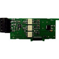
RS485 Serial Communications Output Interface Card With Terminal Block
Manufacturer
Red Lion Controls
Specifications of PAXCDC10
Accessory Type
RS485 Serial Communications Output Interface Card With Terminal Block
Brand/series
PAX Series
Card Type
RS485 Serial Communications Output Card
Data Rate
7⁄8 Bits
Standards
cULus Listed, CSA Certified and CE Marked
Voltage, Working
50 V
Pax Label Kit
189 Different Engineering Units, Labels Inserted Inside the Unit
For Use With
Red Lion PAX Digital Input Panel Meters
Lead Free Status / RoHS Status
Lead free / RoHS Compliant


PAXI SPECIFICATIONS
MAXIMUM SIGNAL FREQUENCIES TABLE
questions with a yes (Y) or no (N). Next determine the Count Mode to be used
for the counter(s). If dual counters are used with different Count Modes, then
the lowest frequency applies to both counters.
Notes:
1. Counter Modes are explained in the Module 1 programming section.
2. If using Rate with single counter with direction or quadrature, assign it to Input A for the listed frequency.
3. * Double the listed value for Rate frequency.
4. Listed values are with frequency DIP switch set on HI frequency.
5. Derate listed frequencies by 20% during serial communications. (Placing a 5 msec. delay between serial characters will eliminate the derating.)
ANNUNCIATORS:
RATE DISPLAY:
COUNTER DISPLAYS:
FUNCTION QUESTIONS
Are any setpoints used?
Is Prescaler Output used?
Is Counter C used?
COUNT MODE
Count x1
Count x2
Quadrature x1
Quadrature x2
Quadrature x4
Rate Only
M
To determine the maximum frequency for the input(s), first answer the
A - Counter A
B - Counter B
C - Counter C
SP1 - setpoint 1 output state
SP2 - setpoint 2 output state
SP3 - setpoint 3 output state
SP4 - setpoint 4 output state
Accuracy: ±0.01%
Minimum Frequency: 0.01 Hz
Maximum Frequency: see Max Signal Frequencies Table.
Maximum Display: 5 Digits: 99999
Adjustable Display (low) Update: 0.1 to 99.9 seconds
Over Range Display: “
Maximum display: 8 digits: ± 99999999 (greater than 6 digits display
Alternates between high order and low order.)
- Rate
- Maximum (High) Rate
- Minimum (Low) Rate
- Upper significant digit display of counter
ODEL
PAXI - 1/8 DIN C
Single: Counter A or B (with/without rate) or Rate only
34
17
22
17
34
N
N
N
8
”
(Values are in KHz)
N/A
25
13
19
13
N
N
Y
6
21
16
20
16
21
N
Y
N
8
N/A
17
12
17
12
N
Y
Y
6
18
12
34
Y
N
N
9
9
4
(Values are in KHz)
N/A
15
10
Y
N
Y
7
7
3
13
21
11
Y
Y
N
8
8
4
5
N/A
10
11
INPUTS A and B:
PRESCALER OUTPUT:
COUNT, RATE AND SLAVE DISPLAY
6-DIGIT 0.56" RED SUNLIGHT READABLE DISPLAY
VARIABLE INTENSITY DISPLAY
10 POINT SCALING (FOR NON-LINEAR PROCESSES)
FOUR SETPOINT ALARM OUTPUTS (W/OPTION CARD)
RETRANSMITTED ANALOG OUTPUT (W/OPTION CARD)
COMMUNICATION AND BUS CAPABILITIES (W/OPTION CARD)
BUS CAPABILITIES; DEVICENET, MODBUS, AND PROFIBUS-DP
CRIMSON PROGRAMMING SOFTWARE
Y
Y
Y
7
6
3
LOGIC: Input trigger levels V
MAGNETIC PICKUP:
DUAL COUNT MODES:
NPN Open Collector: I
OUNTER
Current sinking: Internal 7.8 K pull-up to +12 VDC, I
Current sourcing: Internal 3.9 K pull-down, 7.3 mA max. @ 28 VDC,
Filter: Damping capacitor provided for switch contact bounce. Limits
Sensitivity: 200 mV peak
Hysteresis: 100 mV
Input impedance: 3.9 K @ 60 Hz
Maximum input voltage: ±40 V peak, 30 Vrms
VDC max. With duty cycle of 25% min. and 50 % max.
Dual: Counter A & B or Rate not assigned to active single counter
9 *
7 *
7 *
DIP switch selectable to accept pulses from a variety of sources
including switch contacts, TTL outputs, magnetic pickups and all
standard RLC sensors.
V
input frequency to 50 Hz and input pulse widths to 10 msec. minimum.
When any dual count mode is used, then User Inputs 1 and/or 2 will
accept the second signal of each signal pair. The user inputs do not have
the Logic/Mag, HI/LO Freq, and Sink/Source input setup switches. The
user inputs are inherently a logic input with no low frequency filtering.
Any mechanical contacts used for these inputs in a dual count mode
must be debounced externally. The user input may only be selected for
sink/source by the User Jumper placement.
13
N
N
N
MAX
(Values are in KHz)
= 30 VDC.
7 *
6 *
6 *
12
N
N
Y
SNK
9 *
6 *
6 *
13
N
Y
N
/R
= 100 mA max. @ V
IL
= 1.5 V max.; V
7 *
5 *
5 *
11
N
Y
Y
ATE
5 *
4 *
4 *
Y
N
N
9
(Values are in KHz)
OL
M
IH
3.5 *
3.5 *
7.5
4 *
= 1 VDC max. V
= 3.75 V min.
Y
N
Y
ETER
MAX
3.5 *
3.5 *
5 *
Y
Y
N
9
= 1.9 mA.
OH
4 *
3 *
3 *
Y
Y
Y
7
= 30
Related parts for PAXCDC10
Image
Part Number
Description
Manufacturer
Datasheet
Request
R

Part Number:
Description:
Counter
Manufacturer:
Red Lion Controls
Datasheet:
Part Number:
Description:
Miniature Length Sensor
Manufacturer:
Red Lion Controls
Datasheet:
Part Number:
Description:
Model Lsc - Single Channel Output Length Sensor
Manufacturer:
Red Lion Controls
Datasheet: