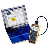
FLUKE-287 CALIBRATED Fluke, FLUKE-287 CALIBRATED Datasheet - Page 39

FLUKE-287 CALIBRATED
Manufacturer Part Number
FLUKE-287 CALIBRATED
Description
MULTIMETER, DIGITAL, HANDHELD
Manufacturer
Fluke
Datasheet
1.FLUKE-287_CALIBRATED.pdf
(88 pages)
Specifications of FLUKE-287 CALIBRATED
Dmm Type
Handheld
Voltage Measuring Range Dc
50 MV To 50 V
Voltage Measuring Range Ac
500 V To 1000 V
Current Measuring Range Dc
500µA To 10A
Current Measuring Range Ac
500µA To 10A
Lead Free Status / RoHS Status
na
To input a temperature offset value, press the softkey labeled
Offset to open a message box with the present offset value. Use
6 and 5 to position the cursor over one of the digits or the polarity
sign. Use 7 and 8 to scroll through the numbers for each digit
in the offset or switch between a + or – offset. With the desired
value displayed, press the softkey labeled OK to set the
temperature offset. When set to something other than 0.0, the
offset value is shown in the secondary display.
Measuring Resistance
The Meter measures resistance (opposition to current flow) in
ohms ( ). This is accomplished by sending a small current out
through the test leads to the circuit under test.
To measure resistance, set the Meter’s rotary switch to
set up the Meter as shown in Figure 15.
To avoid possible damage to the meter or to the
equipment under test, disconnect circuit power
and discharge all high-voltage capacitors before
measuring resistance.
W Caution
S
and
Keep the following in mind when measuring resistance.
Because the meter’s test current flows through all possible paths
between the probe tips, the measured value of a resistor in a
circuit is often different from the resistor’s rated value.
The test leads can add 0.1
measurements. To test the leads, touch the probe tips together
and read the resistance of the leads. To remove lead resistance
from the measurement, hold the test lead tips together and press
the softkey labeled Menu. Next, move the menu selector to the
menu item labeled REL and press the softkey labeled REL. Now
all future displayed readings indicate the resistance at the probe
tips.
The Meter’s resistance function includes modes to help with
resistance measurements. Pressing the softkey labeled Menu
opens a menu of items that can be used to modify the basic
resistance measurement. Refer to the appropriate section in this
manual to learn more about each menu item.
to 0.2
of error to resistance
Making Measurements
29


