IRFL4105PBF International Rectifier, IRFL4105PBF Datasheet - Page 5
IRFL4105PBF
Manufacturer Part Number
IRFL4105PBF
Description
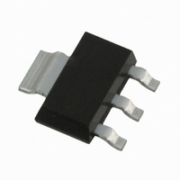
MOSFET N-CH 55V 3.7A SOT223
Manufacturer
International Rectifier
Series
HEXFET®r
Specifications of IRFL4105PBF
Fet Type
MOSFET N-Channel, Metal Oxide
Fet Feature
Logic Level Gate
Rds On (max) @ Id, Vgs
45 mOhm @ 3.7A, 10V
Drain To Source Voltage (vdss)
55V
Current - Continuous Drain (id) @ 25° C
3.7A
Vgs(th) (max) @ Id
4V @ 250µA
Gate Charge (qg) @ Vgs
35nC @ 10V
Input Capacitance (ciss) @ Vds
660pF @ 25V
Power - Max
1W
Mounting Type
Surface Mount
Package / Case
SOT-223 (3 leads + Tab), SC-73, TO-261
Current, Drain
3.7 A
Gate Charge, Total
23 nC
Package Type
SOT-223
Polarization
N-Channel
Power Dissipation
1 W
Resistance, Drain To Source On
0.045 Ohm
Temperature, Operating, Maximum
+150 °C
Temperature, Operating, Minimum
-55 °C
Time, Turn-off Delay
19 ns
Time, Turn-on Delay
7.1 ns
Transconductance, Forward
3.8 S
Voltage, Breakdown, Drain To Source
55 V
Voltage, Forward, Diode
1.3 V
Voltage, Gate To Source
±20 V
Lead Free Status / RoHS Status
Lead free / RoHS Compliant
Other names
*IRFL4105PBF


www.irf.com
1000
0.01
100
0.1
10
0.00001
Fig 9a. Basic Gate Charge Waveform
Fig 9b. Gate Charge Test Circuit
1
10V
12V
V
V
D = 0.50
GS
G
Fig 11. Maximum Effective Transient Thermal Impedance, Junction-to-Ambient
Same Type as D.U.T.
0.05
0.20
0.10
0.02
0.01
Current Regulator
.2µF
Q
(THERMAL RESPONSE)
GS
0.0001
SINGLE PULSE
50KΩ
3mA
Current Sampling Resistors
.3µF
Q
Charge
I
Q
G
GD
G
0.001
D.U.T.
I
D
+
-
V
t , Rectangular Pulse Duration (sec)
DS
1
0.01
0.1
Fig 10a. Switching Time Test Circuit
Fig 10b. Switching Time Waveforms
V
90%
10%
V
1
DS
GS
R
Pulse Width ≤ 1 µs
Duty Factor ≤ 0.1 %
G
10V
V
t
d(on)
GS
Notes:
1. Duty factor D = t / t
2. Peak T = P
V
10
DS
IRFL4105PBF
t
r
J
DM
D.U.T.
100
x Z
1
R
thJA
D
t
2
d(off)
P
DM
+ T
A
1000
t
t
f
1
t 2
+
-
V
DD
10000
5
A
Related parts for IRFL4105PBF
Image
Part Number
Description
Manufacturer
Datasheet
Request
R

Part Number:
Description:
SCHOTTKY RECTIFIER
Manufacturer:
International Rectifier Corp.
Datasheet:
Part Number:
Description:
SCHOTTKY RECTIFIER
Manufacturer:
International Rectifier Corp.
Datasheet:
Part Number:
Description:
SCHOTTKY RECTIFIER
Manufacturer:
International Rectifier Corp.
Datasheet:
Part Number:
Description:
SCHOTTKY RECTIFIER
Manufacturer:
International Rectifier Corp.
Datasheet:
Part Number:
Description:
SCHOTTKY RECTIFIER
Manufacturer:
International Rectifier Corp.
Datasheet:
Part Number:
Description:
SCHOTTKY RECTIFIER
Manufacturer:
International Rectifier Corp.
Datasheet:
Part Number:
Description:
SCHOTTKY RECTIFIER
Manufacturer:
International Rectifier Corp.
Datasheet:
Part Number:
Description:
SCHOTTKY RECTIFIER
Manufacturer:
International Rectifier Corp.
Datasheet:
Part Number:
Description:
SCHOTTKY RECTIFIER
Manufacturer:
International Rectifier Corp.
Datasheet:
Part Number:
Description:
SCHOTTKY RECTIFIER
Manufacturer:
International Rectifier Corp.
Datasheet:
Part Number:
Description:
SCHOTTKY RECTIFIER
Manufacturer:
International Rectifier Corp.
Datasheet:
Part Number:
Description:
SCHOTTKY RECTIFIER
Manufacturer:
International Rectifier Corp.
Datasheet:
Part Number:
Description:
SCHOTTKY RECTIFIER
Manufacturer:
International Rectifier Corp.
Datasheet:
Part Number:
Description:
SCHOTTKY RECTIFIER
Manufacturer:
International Rectifier Corp.
Datasheet:
Part Number:
Description:
SCHOTTKY RECTIFIER
Manufacturer:
International Rectifier Corp.
Datasheet: