STP36NF06FP STMicroelectronics, STP36NF06FP Datasheet
STP36NF06FP
Specifications of STP36NF06FP
Available stocks


Related parts for STP36NF06FP


STP36NF06FP Summary of contents
Page 1
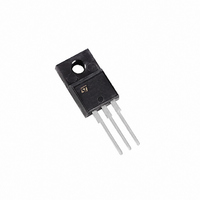
... INTERNAL SCHEMATIC DIAGRAM MARKING STP36NF06 STP36NF06FP STP36NF06 = 25° 100° 120 = 25° 0.47 (1) I 36A, di/dt 400A/µ (2) Starting T STP36NF06 STP36NF06FP - 30A TO-220/TO-220FP TO-220 TO-220FP PACKAGE PACKAGING TO-220 TUBE TO-220FP TUBE Value STP36NF06FP 60 60 ± (*) 0.17 20 200 -55 to 175 (BR)DSS 45V Unit W/°C ...
Page 2
... STP36NF06 STP36NF06FP THERMAL DATA Rthj-case Thermal Resistance Junction-case Rthj-amb Thermal Resistance Junction-ambient T Maximum Lead Temperature For Soldering Purpose l (1.6 mm from case, for 10 sec) ELECTRICAL CHARACTERISTICS (T OFF Symbol Parameter Drain-source V (BR)DSS Breakdown Voltage Zero Gate Voltage I DSS Drain Current ( Gate-body Leakage I GSS ...
Page 3
... SD (*) V Forward On Voltage t Reverse Recovery Time rr Q Reverse Recovery Charge rr I Reverse Recovery Current RRM (*) Pulsed: Pulse duration = 300 µs, duty cycle 1 Pulse width limited by safe operating area. Safe Operating Area for TO-220 STP36NF06 STP36NF06FP Test Conditions Min 4 (Resistive Load, Figure 3) V ...
Page 4
... STP36NF06 STP36NF06FP Thermal Impedance Output Characteristics Transconductance 4/9 Thermal Impedance for TO-220FP Transfer Characteristics Static Drain-source On Resistance ...
Page 5
... Gate Charge vs Gate-source Voltage Normalized Gate Threshold Voltage vs Temperature Source-drain Diode Forward Characteristics STP36NF06 STP36NF06FP Capacitance Variations Normalized on Resistance vs Temperature Normalized Breakdown Voltage Temperature 5/9 ...
Page 6
... STP36NF06 STP36NF06FP Fig. 1: Unclamped Inductive Load Test Circuit Fig. 1: Unclamped Inductive Load Test Circuit Fig. 3: Switching Times Test Circuits For Resistive Load Fig. 5: Test Circuit For Inductive Load Switching And Diode Recovery Times 6/9 Fig. 2: Unclamped Inductive Waveform Fig. 4: Gate Charge test Circuit ...
Page 7
... E 0.45 F 0.75 F1 1.15 F2 1.15 G 4. 28.6 L4 9 Ø ¯ STP36NF06 STP36NF06FP MAX. MIN. 4.6 0.173 2.7 0.098 2.75 0.098 0.7 0.017 1 0.030 1.7 0.045 1.7 0.045 5.2 0.195 2.7 0.094 10.4 0.393 30.6 1.126 10.6 0.385 16.4 0.626 9 ...
Page 8
... STP36NF06 STP36NF06FP DIM. MIN. A 4.4 C 1.23 D 2.40 E 0.49 F 0.61 F1 1.14 F2 1.14 G 4. 2.65 L6 15.25 L7 6.20 L9 3.50 DIA 3.75 8/9 TO-220 MECHANICAL DATA mm. TYP. MAX. MIN. 4.6 0.173 1.32 0.048 2.72 0.094 0.70 0.019 0.88 0.024 1.70 0.044 1.70 0.044 5.15 ...
Page 9
... All other names are the property of their respective owners. Australia - Belgium - Brazil - Canada - China - Czech Republic - Finland - France - Germany - Hong Kong - India - Israel - Italy - Japan - Malaysia - Malta - Morocco -Singapore - Spain - Sweden - Switzerland - United Kingdom - United States. 2003 STMicroelectronics - All Rights Reserved STMicroelectronics GROUP OF COMPANIES www.st.com STP36NF06 STP36NF06FP 9/9 ...