12065E104ZAT2A AVX Corporation, 12065E104ZAT2A Datasheet - Page 37
12065E104ZAT2A
Manufacturer Part Number
12065E104ZAT2A
Description
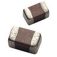
Cap Ceramic 0.1uF 50VDC Z5U -20% to 80% SMD 1206 Paper T/R
Manufacturer
AVX Corporation
Type
Flatr
Series
1206r
Specifications of 12065E104ZAT2A
Package/case
1206
Mounting
Surface Mount
Capacitance Value
0.1 uF
Dielectric
Z5U
Voltage
50 Vdc
Product Length
3.2 mm
Product Height
1.5(Max) mm
Product Depth
1.6 mm
Tolerance
-20 to 80 %
Dielectric Characteristic
Z5U
Capacitance
0.1µF
Capacitance Tolerance
+80, -20%
Voltage Rating
50VDC
Capacitor Case Style
1206
No. Of Pins
2
Capacitor Mounting
SMD
Rohs Compliant
Yes
Case Code
1206
Case Size
1206
Material, Element
Ceramic
Termination
SMT
Operating Temperature Range
+ 10 C to + 85 C
Temperature Coefficient / Code
Z5U
Package / Case
1206 (3216 metric)
Product
General Type MLCCs
Dimensions
1.6 mm (0.063 in) W x 3.2 mm (0.126 in) L
Dissipation Factor Df
4
Termination Style
SMD/SMT
Lead Free Status / Rohs Status
RoHS Compliant part


Embossed Carrier Configuration
8 & 12mm Tape Only
8 & 12mm Embossed Tape
Metric Dimensions Will Govern
CONSTANT DIMENSIONS
VARIABLE DIMENSIONS
NOTES:
1. A
2. Tape with components shall pass around radius “R” without damage. The minimum trailer length (Note 2 Fig. 3) may require additional length to provide R min. for 12 mm
3. G
4. G
5. The embossment hole location shall be measured from the sprocket hole controlling the location of the embossment.
6. B
36
Tape Size
Tape Size
clearance between the end of the terminals or body of the component to the sides and depth of the cavity (A
(.020) max. The clearance allowed must also prevent rotation of the component within the cavity of not more than 20 degrees (see sketches C & D).
embossed tape for reels with hub diameters approaching N min. (Table 4).
cavity whichever is less.
or to the edge of the cavity whichever is less.
Dimensions of embossment location and hole location shall be applied independent of each other.
1/2 Pitch
0
1
1
2
Double
, B
12mm
12mm
12mm
dimension is a reference dimension for tape feeder clearance only.
dimension is the flat area from the edge of the sprocket hole to either the outward deformation of the carrier tape between the embossed cavities or to the edge of the
dimension is the flat area from the edge of the carrier tape opposite the sprocket holes to either the outward deformation of the carrier tape between the embossed cavity
8mm
8mm
8mm
Pitch
and
0
, and K
0
are determined by the max. dimensions to the ends of the terminals extending from the component body and/or the body dimensions of the component. The
See Note 6 See Note 5
(.059
8.4
(.179)
(.323)
(.179)
(.323)
Max.
4.55
4.55
8.2
8.2
D
B
+0.10
-0.0
0
1
+.004
-0.0
)
(.069 ± .004) (.157 ± .004) (.079 ± .002)
1.75 ± 0.10
(.039)
(.059)
(.039)
(.059)
Min.
1.0
1.5
1.0
1.5
D
E
1
(.138 ± .002) (.157 ± .004)
(.217 ± .002) (.157 ± .004)
(.138 ± .002) 0.79 ± .004
(.217 ± .002) (.315 ± .004)
4.0 ± 0.10
3.5 ± 0.05
5.5 ± 0.05
3.5 ± 0.05
5.5 ± 0.05
P
F
0
4.0 ± 0.10
4.0 ± 0.10
2.0 ± 0.10
8.0 ± 0.10
2.0 ± 0.05
P
P
2
1
See Note 2
T Max.
(1.181)
(1.181)
0.600
(.024)
(.984)
(.984)
Min.
25
30
25
30
R
0
, B
0
, and K
6.5 Max.
2.5 Max.
6.5 Max.
2.5 Max
0
(.004)
(.098)
(.256)
(.098)
(.256)
Max.
) must be within 0.05 mm (.002) min. and 0.50 mm
0.10
T
T
1
2
(.472 ± .012)
(.472 ± .012)
See Note 3
12.0 ± .30
12.0 ± .30
(.315
(.315
(.030)
8.0
0.75
Min.
8.0
G
W
1
+0.3
+0.3
-0.1
-0.1
+.012
+.012
-.004
-.004
)
)
See Note 4
See Note 1
See Note 1
See Note 1
See Note 1
A
(.030)
0
0.75
Min.
G
B
2
0
K
0
Related parts for 12065E104ZAT2A
Image
Part Number
Description
Manufacturer
Datasheet
Request
R

Part Number:
Description:
Manufacturer:
AVX Corporation
Datasheet:
Part Number:
Description:
Manufacturer:
AVX Corporation
Datasheet:
Part Number:
Description:
Manufacturer:
AVX Corporation
Datasheet:
Part Number:
Description:
Manufacturer:
AVX Corporation
Datasheet:
Part Number:
Description:
Manufacturer:
AVX Corporation
Datasheet: