12065E104ZAT2A AVX Corporation, 12065E104ZAT2A Datasheet - Page 47
12065E104ZAT2A
Manufacturer Part Number
12065E104ZAT2A
Description
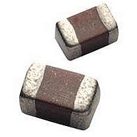
Cap Ceramic 0.1uF 50VDC Z5U -20% to 80% SMD 1206 Paper T/R
Manufacturer
AVX Corporation
Type
Flatr
Series
1206r
Specifications of 12065E104ZAT2A
Package/case
1206
Mounting
Surface Mount
Capacitance Value
0.1 uF
Dielectric
Z5U
Voltage
50 Vdc
Product Length
3.2 mm
Product Height
1.5(Max) mm
Product Depth
1.6 mm
Tolerance
-20 to 80 %
Dielectric Characteristic
Z5U
Capacitance
0.1µF
Capacitance Tolerance
+80, -20%
Voltage Rating
50VDC
Capacitor Case Style
1206
No. Of Pins
2
Capacitor Mounting
SMD
Rohs Compliant
Yes
Case Code
1206
Case Size
1206
Material, Element
Ceramic
Termination
SMT
Operating Temperature Range
+ 10 C to + 85 C
Temperature Coefficient / Code
Z5U
Package / Case
1206 (3216 metric)
Product
General Type MLCCs
Dimensions
1.6 mm (0.063 in) W x 3.2 mm (0.126 in) L
Dissipation Factor Df
4
Termination Style
SMD/SMT
Lead Free Status / Rohs Status
RoHS Compliant part


46
Surface Mounting Guide
MLC Chip Capacitors
APPLICATION NOTES
Storage
Good solderability is maintained for at least twelve months,
provided the components are stored in their “as received”
packaging at less than 40°C and 70% RH.
Solderability
Terminations to be well soldered after immersion in a 60/40
tin/lead solder bath at 235 ±5°C for 2±1 seconds.
Leaching
Terminations will resist leaching for at least the immersion
times and conditions shown below.
Recommended Soldering Profiles
Termination Type
Nickel Barrier
Wave
Reflow
300
250
200
150
100
300
250
200
150
100
50
50
0
0
(Preheat chips before soldering)
T/maximum 150 C
(Minimize soldering time)
1min
Tin/Lead/Silver Temp. °C
1 to 2 min
Preheat
T
Preheat
60/40/0
Solder
1min
3 sec. max
10 sec. max
230 C
250 C
Solder
260±5
220 C
250 C
to
to
Natural
Cooling
Natural
Cooling
Immersion Time
Seconds
30±1
General
Surface mounting chip multilayer ceramic capacitors
are designed for soldering to printed circuit boards or other
substrates. The construction of the components is such that
they will withstand the time/temperature profiles used in both
wave and reflow soldering methods.
Handling
Chip multilayer ceramic capacitors should be handled with
care to avoid damage or contamination from perspiration
and skin oils. The use of tweezers or vacuum pick ups
is strongly recommended for individual components. Bulk
handling should ensure that abrasion and mechanical shock
are minimized. Taped and reeled components provides the
ideal medium for direct presentation to the placement
machine. Any mechanical shock should be minimized during
handling chip multilayer ceramic capacitors.
Preheat
It is important to avoid the possibility of thermal shock during
soldering and carefully controlled preheat is therefore
required. The rate of preheat should not exceed 4°C/second
and a target figure 2°C/second is recommended. Although
an 80°C to 120°C temperature differential is preferred,
recent developments allow a temperature differential
between the component surface and the soldering temper-
ature of 150°C (Maximum) for capacitors of 1210 size and
below with a maximum thickness of 1.25mm. The user is
cautioned that the risk of thermal shock increases as chip
size or temperature differential increases.
Soldering
Mildly activated rosin fluxes are preferred. The minimum
amount of solder to give a good joint should be used.
Excessive solder can lead to damage from the stresses
caused by the difference in coefficients of expansion
between solder, chip and substrate. AVX terminations are
suitable for all wave and reflow soldering systems. If hand
soldering cannot be avoided, the preferred technique is the
utilization of hot air soldering tools.
Cooling
Natural cooling in air is preferred, as this minimizes stresses
within the soldered joint. When forced air cooling is used,
cooling rate should not exceed 4°C/second. Quenching
is not recommended but if used, maximum temperature
differentials should be observed according to the preheat
conditions above.
Cleaning
Flux residues may be hygroscopic or acidic and must be
removed. AVX MLC capacitors are acceptable for use with
all of the solvents described in the specifications MIL-STD-
202 and EIA-RS-198. Alcohol based solvents are acceptable
and properly controlled water cleaning systems are also
acceptable. Many other solvents have been proven successful,
and most solvents that are acceptable to other components
on circuit assemblies are equally acceptable for use with
ceramic capacitors.
Related parts for 12065E104ZAT2A
Image
Part Number
Description
Manufacturer
Datasheet
Request
R

Part Number:
Description:
Manufacturer:
AVX Corporation
Datasheet:
Part Number:
Description:
Manufacturer:
AVX Corporation
Datasheet:
Part Number:
Description:
Manufacturer:
AVX Corporation
Datasheet:
Part Number:
Description:
Manufacturer:
AVX Corporation
Datasheet:
Part Number:
Description:
Manufacturer:
AVX Corporation
Datasheet: