SD2942 STMicroelectronics, SD2942 Datasheet
SD2942
Specifications of SD2942
SD2942
Available stocks


Related parts for SD2942


SD2942 Summary of contents
Page 1
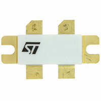
... MHz OUT ■ Low R DS(on) Description The SD2942 is a gold metallized N-channel MOS field-effect RF power transistor. The SD2942 offers 25% lower R than industry standard ds(ON) and 20% higher power saturation than ST SD2932. These characteristics make the SD2942 ideal for 50V DC very high power application up to 250 MHz ...
Page 2
... Content Content 1 Electrical data . . . . . . . . . . . . . . . . . . . . . . . . . . . . . . . . . . . . . . . . . . . . . . 3 1.1 Maximum rating . . . . . . . . . . . . . . . . . . . . . . . . . . . . . . . . . . . . . . . . . . . . . 3 1.2 Thermal data . . . . . . . . . . . . . . . . . . . . . . . . . . . . . . . . . . . . . . . . . . . . . . . 3 2 Electrical characteristics . . . . . . . . . . . . . . . . . . . . . . . . . . . . . . . . . . . . . 4 3 Impedance . . . . . . . . . . . . . . . . . . . . . . . . . . . . . . . . . . . . . . . . . . . . . . . . . 5 4 Typical performance . . . . . . . . . . . . . . . . . . . . . . . . . . . . . . . . . . . . . . . . . 6 5 Test circuit . . . . . . . . . . . . . . . . . . . . . . . . . . . . . . . . . . . . . . . . . . . . . . . . 10 6 Package mechanical data . . . . . . . . . . . . . . . . . . . . . . . . . . . . . . . . . . . . 13 7 Revision history . . . . . . . . . . . . . . . . . . . . . . . . . . . . . . . . . . . . . . . . . . . 15 2/16 Doc ID 11736 Rev 3 SD2942 ...
Page 3
... SD2942 1 Electrical data 1.1 Maximum rating T = 25° C CASE Table 2. Absolute maximum rating Symbol (1) V Drain source voltage (BR)DSS (1) V Drain-gate voltage (R DGR V Gate-source voltage GS I Drain current D P Power dissipation DISS T Max. operating junction temperature J T Storage temperature STG 150 ° ...
Page 4
... MHz MHz DS Test Conditions I = 500 175MHz 500 350 175MHz DQ OUT I = 500 350 175MHz DQ OUT I = 500 mA P 350 175MHz DQ OUT = Doc ID 11736 Rev 3 SD2942 Min. Typ. Max. Unit 130 V µA 100 250 mho 415 pF 236 Min. Typ. Max. Unit 350 W 15 ...
Page 5
... SD2942 3 Impedance Figure 2. Impedance data schematic Table 6. Impedance data f 250 MHz 230 MHz 200 MHz 175 MHz 100 MHz 50 MHz Typical Input Impedance (Ω 1.9 1 1.8 1 1.6 1 1.4 1 2.5 3 4.4 Doc ID 11736 Rev 3 Impedance Typical Drain Load Impedance S Z (Ω ...
Page 6
... Doc ID 11736 Rev 3 Drain current vs gate voltage Vds = +80 ° +25 ° -20 ° Vgs (V) Power gain vs Pout and case temperature Vdd = 50V Idq = 2 x 250mA Freq = 175 MHz 50 100 150 200 250 300 350 400 Pout (W) SD2942 6 -20°C +25°C +80°C 450 500 ...
Page 7
... SD2942 Figure 7. Efficiency vs case temperature 100 150 200 250 Pout (W) Figure 9. Pout vs input power and drain voltage 500 450 400 350 300 250 200 150 100 Pin (W) Figure 8. 500 +25°C 450 -20°C 400 +80°C 350 300 250 200 150 100 Vdd = 50V ...
Page 8
... Vdd (V) Figure 13. Maximum safe operating area 8/16 Figure 12. Maximum thermal resist vs case 0.42 Pin = 10W 0.40 Pin = 7W 0.38 Pin = 5W 0.36 Freq = 175 MHz Idq = 2 x 250mA 0. Doc ID 11736 Rev 3 temperature SD2942 ...
Page 9
... SD2942 Figure 14. Transient thermal impedance Figure 15. Transient thermal model Doc ID 11736 Rev 3 Typical performance 9/16 ...
Page 10
... Test circuit 5 Test circuit Figure 16. 175 MHz test circuit schematic Note: 1 Dimension at component symbol are reference for component placement. 2 Gap between ground and transmission lines is + 0.002{0.05} - 0.000{0.00} Typ. 10/16 Doc ID 11736 Rev 3 SD2942 ...
Page 11
... SD2942 Table 7. 175 MHz test circuit component part list Symbol R1,R2,R5,R6 R3,R4 R7,R8 R9,R10 C1,C4 C2,C3,C7,C8,C17,C19,C20,C21 C5 C6 C9,C10 C11,C12, C13 C14,C15,C24,C25 C16,C18 C22,C23 C26,C27 C28 FB1,FB5 FB2,FB6 FB3 FB4 PCB Description 470 Ω surface mount chip resistor 360 Ω 0.5 W, carbon comp. axial lead resistor or equivalent 560 Ω ...
Page 12
... Test circuit Figure 17. 175 MHz test circuit photomaster Figure 18. 175 MHz test circuit 12/16 8.50 inches Doc ID 11736 Rev 3 SD2942 ...
Page 13
... SD2942 6 Package mechanical data In order to meet environmental requirements, ST offers these devices in different grades of ® ECOPACK packages, depending on their level of environmental compliance. ECOPACK specifications, grade definitions and product status are available at: www.st.com. ECOPACK trademark. Table 8. M244 (.400 x .860 4/L BAL N/HERM W/FLG) DIM ...
Page 14
... Package mechanical data Figure 19. M244 package dimensions ng Dimension: Inches 14/16 Doc ID 11736 Rev 3 SD2942 ...
Page 15
... SD2942 7 Revision history Table 9. Document revision history Date 18-Oct-2005 04-Jan-2006 14-Apr-2010 Revision 1 First Issue. 2 Complete version. Figure 13, Figure 14 3 Added Doc ID 11736 Rev 3 Revision history Changes Figure 15. and 15/16 ...
Page 16
... Australia - Belgium - Brazil - Canada - China - Czech Republic - Finland - France - Germany - Hong Kong - India - Israel - Italy - Japan - Malaysia - Malta - Morocco - Philippines - Singapore - Spain - Sweden - Switzerland - United Kingdom - United States of America 16/16 Please Read Carefully: © 2010 STMicroelectronics - All rights reserved STMicroelectronics group of companies www.st.com Doc ID 11736 Rev 3 SD2942 ...