SD2918 STMicroelectronics, SD2918 Datasheet
SD2918
Specifications of SD2918
SD2918
Available stocks


Related parts for SD2918


SD2918 Summary of contents
Page 1
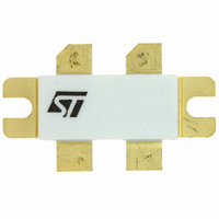
... Excellent thermal stability ■ Common source configuration ■ min. with 18 dB gain @ 30 MHz OUT Description The SD2918 is a n-channel MOS field-effect RF power transistor intended for use large signal applications up to 200 MHz. Table 1. Device summary Order code SD2918 November 2009 Figure 1. ...
Page 2
... Electrical data . . . . . . . . . . . . . . . . . . . . . . . . . . . . . . . . . . . . . . . . . . . . . . 3 1.1 Maximum ratings . . . . . . . . . . . . . . . . . . . . . . . . . . . . . . . . . . . . . . . . . . . . 3 1.2 Thermal data . . . . . . . . . . . . . . . . . . . . . . . . . . . . . . . . . . . . . . . . . . . . . . . 3 2 Electrical characteristics . . . . . . . . . . . . . . . . . . . . . . . . . . . . . . . . . . . . . 4 2.1 Static . . . . . . . . . . . . . . . . . . . . . . . . . . . . . . . . . . . . . . . . . . . . . . . . . . . . . 4 2.2 Dynamic . . . . . . . . . . . . . . . . . . . . . . . . . . . . . . . . . . . . . . . . . . . . . . . . . . . 4 3 Impedance data . . . . . . . . . . . . . . . . . . . . . . . . . . . . . . . . . . . . . . . . . . . . . 5 4 Typical performances . . . . . . . . . . . . . . . . . . . . . . . . . . . . . . . . . . . . . . . . 6 5 Test circuit and BOM list . . . . . . . . . . . . . . . . . . . . . . . . . . . . . . . . . . . . . 8 6 Circuit layout . . . . . . . . . . . . . . . . . . . . . . . . . . . . . . . . . . . . . . . . . . . . . . 10 7 Package mechanical data . . . . . . . . . . . . . . . . . . . . . . . . . . . . . . . . . . . . 11 8 Revision history . . . . . . . . . . . . . . . . . . . . . . . . . . . . . . . . . . . . . . . . . . . 13 2/14 Doc ID 6866 Rev 2 SD2918 ...
Page 3
... SD2918 1 Electrical data 1.1 Maximum ratings Table 2. Absolute maximum ratings (T Symbol V Drain source voltage (BR)DSS V Drain-gate voltage (R DGR V Gate-source voltage GS I Drain current D P Power dissipation DISS T Max. operating junction temperature J T Storage temperature STG 1.2 Thermal data Table 3. Thermal data ...
Page 4
... MHz MHz MHz DS Test conditions = 100 mA MHz 0.475 100 mA MHz out = 100 mA MHz out = 100 mA MHz out Doc ID 6866 Rev 2 SD2918 Min Typ Max Unit 125 V 1 µA 1.0 5.0 V 5.0 V 0.8 mho 58 pF 35.5 pF 7.5 pF Min Typ Max Unit ...
Page 5
... SD2918 3 Impedance data Figure 2. Impedance data Table 6. Impedance data Freq 30 MHz Typical Input Impedance (Ω 13.4 Doc ID 6866 Rev 2 Impedance data Typical Drain Load Impedance S Z (Ω 7.2 5/14 ...
Page 6
... Typical performances 4 Typical performances Figure 3. Capacitance vs drain-source voltage Figure 5. Drain current vs gate voltage Figure 7. Output power vs input power 6/14 Figure 4. Maximum thermal resistance vs case temperature Figure 6. Gate-source voltages vs case temperature Figure 8. Output power vs input power at different T Doc ID 6866 Rev 2 SD2918 C ...
Page 7
... SD2918 Figure 9. Output power vs supply voltage Figure 11. Power gain and efficiency vs output power Figure 10. Output power vs gate voltage Doc ID 6866 Rev 2 Typical performances 7/14 ...
Page 8
... XICON VENKEL FAIR-RITE CORP. Multi-aperture core FAIR-RITE CORP. Shield bead surface mount EMI FAIR-RITE CORP. Shield bead surface mount EMI BELDEN ALPHA BELDEN Doc ID 6866 Rev 2 SD2918 +50V + RF OUTPUT Description 100 Ω surface mount chip resistor 160 Ω carbon film axial-lead resistor 160 Ω ...
Page 9
... SD2918 Table 7. Bill of material (continued) Component C10 SKA100M160 C9 C1812X7R501-103KNE C8 C1812X7R501-103KNE C7 C1812X7R501-103KNE C6 RVS-50V100M-R C5 C1812X7R501-103KNE C4 ATC200B103KW50X C3 463 C2 ATC200B103KW50X C1 ATC200B103KW50X T2 T1 PCB G0300M1026 Part n. Supplier MALLORY VENKEL VENKEL VENKEL ELNA VENKEL ATC ARCO ATC ATC ROGERS CORP. Doc ID 6866 Rev 2 Test circuit and BOM list Description 10 µ ...
Page 10
... Circuit layout 6 Circuit layout Figure 13. 30 MHz test circuit photomaster Figure 14. 30 MHz production test fixture 10/14 Doc ID 6866 Rev 2 SD2918 REF. 7143542A ...
Page 11
... SD2918 7 Package mechanical data In order to meet environmental requirements, ST offers these devices in different grades of ® ECOPACK packages, depending on their level of environmental compliance. ECOPACK specifications, grade definitions and product status are available at: www.st.com. ® ECOPACK trademark. Doc ID 6866 Rev 2 Package mechanical data ® ...
Page 12
... Doc ID 6866 Rev 2 SD2918 Inch Min Typ Max 0.220 0.230 0.780 0.820 0.720 0.730 0.970 0.980 0.370 0.385 0.004 0.006 0.085 0.105 0.160 ...
Page 13
... SD2918 8 Revision history Table 9. Document revision history Date 21-Jun-2004 05-Nov-2009 Revision 1 First release 2 Updated marking on Doc ID 6866 Rev 2 Revision history Changes Table 1. 13/14 ...
Page 14
... Australia - Belgium - Brazil - Canada - China - Czech Republic - Finland - France - Germany - Hong Kong - India - Israel - Italy - Japan - Malaysia - Malta - Morocco - Philippines - Singapore - Spain - Sweden - Switzerland - United Kingdom - United States of America 14/14 Please Read Carefully: © 2009 STMicroelectronics - All rights reserved STMicroelectronics group of companies www.st.com Doc ID 6866 Rev 2 SD2918 ...