ZY8140G-R1 POWER ONE, ZY8140G-R1 Datasheet - Page 21
ZY8140G-R1
Manufacturer Part Number
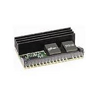
ZY8140G-R1
Description
Module DC-DC 1-OUT 0.5V to 5.5V 40A 17-Pin SIP
Manufacturer
POWER ONE
Type
Step Downr
Datasheet
1.ZY8140G.pdf
(30 pages)
Specifications of ZY8140G-R1
Number Of Outputs
1
Output Voltage
0.5 to 5.5 V
Package
17SIP
Output Current
40 A
Input Voltage
8 to 14 V
Switching Regulator
Yes
Output Power
220 W
Input Voltage Range
8 V to 14 V
Output Voltage (channel 1)
0.5 V to 5.5 V
Output Current (channel 1)
40 A
Package / Case Size
SIP
Package / Case
SIP
Product
Non-Isolated / POL
Lead Free Status / Rohs Status
Lead free / RoHS Compliant


8.3.4.1
Z-Series POLs can be arranged in several groups to
simplify fault management.
defined as a number of POLs with interconnected
OK pins. A group can include from 1 to 32 POLs. If
fault propagation within a group is desired, the
propagation bit needs to be checked in the GUI Fault
Management Window. The parameters can also be
programmed directly via the I
the PC3 register shown in Figure 33.
When propagation is enabled, the faulty POL pulls its
OK pin low. A low OK line initiates turn-off of other
POLs in the group.
In addition, the OK lines can be connected to the
DPM to facilitate propagation of faults and errors
between groups.
independent groups.
between groups, the respective bit needs to be
checked in the GUI Fault and Error Propagation
window shown in Figure 34.
ZD-01977 Rev. 1.1, 01-Jul-10
Bit 7
Bit 6
Bit 5
Bit 4
Bit 3
Bit 2
Bit 1
Bit 0
R/W-0
PTM
Bit 7
Figure 33. Protection Configuration Register PC3
PTM : Temperature warning Message
1 = enabled
0 = disabled
PGM: Power good message
1 = enabled
0 = disabled
TRP : Tracking fault propagation
1 = enabled
0 = disabled
OTP: Overtemperature fault propagation
1 = enabled
0 = disabled
OCP: Overcurrent fault propagation
1 = enabled
0 = disabled
UVP: Undervoltage fault propagation
1 = enabled
0 = disabled
OVP : Overvoltage error propagation
1 = enabled
0 = disabled
PVP : Phase voltage error propagation (Not Active)
1 = enabled
0 = disabled
R/W-0
PGM
Grouping of POLs
R/W-1
TRP
One DPM can control up to 4
R/W-1
OTP
To enable fault propagation
R/W-1
OCP
2
A group of POLs is
C bus by writing into
R/W-1
UVP
R = Readable bit
W = Writable bit
U = Unimplemented bit,
- n = Value at POR reset
read as ‘0’
www.power-one.com
R/W-1
OVP
R/W-1
PVP
Bit 0
8V to 14V Input
In this case low OK line will signal DPM to pull other
OK lines low to initiate shutdown of other POLs as
programmed in the GUI Fault and Error Propagation
window. If an error is propagated, the DPM can also
generate commands to turn off a front end (a DC-DC
converter generating the intermediate bus voltage)
and trigger an optional crowbar protection to
accelerate removal of the IBV voltage.
8.3.4.2
Propagation of a fault (OCP, UVP, OTP, and TRP)
initiates regular turn-off of other POLs. The faulty
POL in this case performs either the regular or the
fast turn-off depending on a specific fault as
described in section 8.3.2.
Propagation of an error initiates fast turn-off of other
POLs. The faulty POL performs the fast turn-off and
turns on its low side switch.
Example of the fault propagation is shown in Figure
35 - Figure 36. In this three-output system (refer to
the block diagram in Figure 16), the POL powering
the output V3 (Ch 1 in the picture) encounters the
undervoltage fault after the turn-on. When the fault
propagation is not enabled, the POL turns off and
generates the UV fault signal. Because the UV fault
triggers the regular turn off, the POL meets its turn-
off delay and falling slew rate settings during the
turn-ff process as shown in Figure 35. Since the UV
fault is programmed to be non-latching, the POL will
attempt to restart every 130ms, repeating the
process described above until the condition causing
the undervoltage is removed.
If the fault propagation between groups is enabled,
the POL powering the output V3 pulls its OK line low
and the DPM propagates the signal to the POL
powering the output V1 that belongs to other group.
ZY8140 40A DC-DC Intelligent POL
Figure 34. Fault and Error Propagation Window
Propagation Process
0.5V to 3.65V Output
Page 21 of 30
Data Sheet
Related parts for ZY8140G-R1
Image
Part Number
Description
Manufacturer
Datasheet
Request
R

Part Number:
Description:
PROGBL CONVERT DC-DC 40A OUT SMD
Manufacturer:
POWER ONE
Datasheet:

Part Number:
Description:
Zy8140 40a Dc-dc Intelligent Pol
Manufacturer:
Power-One
Datasheet:

Part Number:
Description:
SWITCHING POWER SUPPLIES, SINGLE OUTPUT, 80 WATTS
Manufacturer:
POWER ONE
Datasheet:
Part Number:
Description:
HAS SERIES - 30 WATT
Manufacturer:
POWER ONE
Datasheet:
Part Number:
Description:
SINGLE OUTPUT
Manufacturer:
POWER ONE
Datasheet:
Part Number:
Description:
BRS DC/DC converters(1.5 WATT)
Manufacturer:
Power-One
Datasheet:
Part Number:
Description:
3...15 Watt DC-DC Converter
Manufacturer:
Power-One
Datasheet:
Part Number:
Description:
HBS SERIES - 100 WATT
Manufacturer:
Power-One
Datasheet:
Part Number:
Description:
3...15 Watt DC-DC Converter
Manufacturer:
Power-One
Datasheet:
Part Number:
Description:
BUS DC/DC converters(3 WATT)
Manufacturer:
Power-One
Datasheet:
Part Number:
Description:
HES SERIES 150 WATT
Manufacturer:
Power-One
Datasheet: