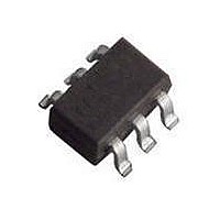
BGA2717 T/R NXP Semiconductors, BGA2717 T/R Datasheet - Page 4

BGA2717 T/R
Manufacturer Part Number
BGA2717 T/R
Description
RF Amplifier TAPE-7 MMIC-RFSS
Manufacturer
NXP Semiconductors
Type
Generic 50 Ohm Gain Blockr
Datasheet
1.BGA2717115.pdf
(14 pages)
Specifications of BGA2717 T/R
Operating Frequency
1 GHz
Noise Figure
2.3 dB
Bandwidth
3200 MHz
Operating Supply Voltage
5 V
Supply Current
8 mA
Maximum Power Dissipation
200 mW
Maximum Operating Temperature
+ 150 C
Mounting Style
SMD/SMT
Package / Case
SOT-363
Number Of Channels
1 Channel
Lead Free Status / RoHS Status
Lead free / RoHS Compliant
Other names
BGA2717,115
Philips Semiconductors
8. Application information
9397 750 13293
Product data sheet
Figure 1
internally matched to 50 , and therefore does not need any external matching. The value
of the input and output DC blocking capacitors C2 and C3 should not be more than 100 pF
for applications above 100 MHz. However, when the device is operated below 100 MHz,
the capacitor value should be increased.
The 22 nF supply decoupling capacitor C1 should be located as close as possible to the
MMIC.
The printed-circuit board (PCB) top ground plane, connected to pins 2, 4 and 5 must be as
close as possible to the MMIC, and ideally directly beneath it. When using via holes, use
multiple via holes, located as close as possible to the MMIC.
Figure 2
Fig 1. Typical application circuit.
shows a typical application circuit for the BGA2717 MMIC. The device is
shows the PCB layout, used for the standard demonstration board.
Rev. 02 — 24 September 2004
RF input
V
S
C2
C1
6
RF_IN
GND1
4
V
1
S
GND2
2, 5
RF_OUT
3
C3
© Koninklijke Philips Electronics N.V. 2004. All rights reserved.
mgu435
RF output
MMIC wideband amplifier
BGA2717
4 of 14


