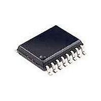
UAA3201TD-T NXP Semiconductors, UAA3201TD-T Datasheet - Page 9

UAA3201TD-T
Manufacturer Part Number
UAA3201TD-T
Description
RF Transceiver REMOTE CONTROL RECVR
Manufacturer
NXP Semiconductors
Datasheet
1.UAA3201TD-T.pdf
(20 pages)
Specifications of UAA3201TD-T
Operating Supply Voltage
5 V
Mounting Style
SMD/SMT
Package / Case
SO-16
Minimum Operating Temperature
- 40 C
Lead Free Status / RoHS Status
Lead free / RoHS Compliant
Other names
UAA3201T/V1,118
Philips Semiconductors
Table 1 Test signals
Test results
P
power from signal generator 2 at the input of the test board.
Table 2 Test results
Notes
1. The supply voltage V
2. Differential probe of spectrum analyser connected to pins MOP and MON.
3. Probe of spectrum analyser connected to pin LIN.
4. Spectrum analyser connected to the input of the test board.
5. Probe of spectrum analyser connected to either pin MOP or pin MON.
2000 Apr 18
Maximum input power;
see Fig.4
Receiver turn-on time;
see Fig.4 and note 1
Interception point (mixer);
see Fig.5 and note 2
Interception point (mixer plus
IF amplifier); see Fig.5 and
note 3
Spurious radiation; see Fig.6
and note 4
1 dB compression point
(mixer);
see Fig.7 and note 5
1
UHF/VHF remote control receiver
is the maximum available power from signal generator 1 at the input of the test board; P
SIGNAL
TEST
1
2
3
TEST
FREQUENCY
433.92
434.02
433.92
(MHz)
CC
of the test circuit alternates between ‘on’ (100 ms) and ‘off’ (100 ms); see Fig.3.
250 bits/s
(square wave)
test signal 1;
P
(minimum P
test signal 1;
P
test signal 3;
P
test signal 3;
P
test signal 3;
P
P
(minimum P
DATA SIGNAL
1
1
1
1
11
12
= 30 dBm
= P
= 50 dBm
= 50 dBm
= 70 dBm;
= 38 dBm
ref
GENERATOR
1
+ 10 dB
max
1dB
)
)
RZ signal with duty cycle of 66% for logic 1;
RZ signal with duty cycle of 33% for logic 0
no modulation
no modulation
test
signal 2;
P
test
signal 2;
P
2
2
= P
= P
2
9
1
1
BER
(e.g. 7.5 bit errors per second for 250 bits/s)
check that the first 10 bits are correct; error counting is
started 10 ms after V
IP3 = P
minimum value: IP3
IP3 = P
minimum value: IP3
no spurious radiation (25 MHz to 1 GHz) with level
higher than 60 dBm (maximum P
(P
where P
and P
o1
MODULATION
+ 70 dB)
o2
3
1
1
o1
is the output power for test signal with P
+
+
is the output power for test signal with P
10
1
1
2
2
2
IM3 (dB);
IM3 (dB);
[P
o2
mix
IF
+ 38 dB (minimum P
CC
RESULT
is switched on
38 dBm
20 dBm
2
is the maximum available
Product specification
spur
UAA3201T
)
100%
MODULATION
1dB
INDEX
)]
1 dB,
12
11


