104130-4 TE Connectivity, 104130-4 Datasheet - Page 235
104130-4
Manufacturer Part Number
104130-4
Description
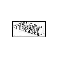
Conn Ejector Header HDR 20 POS 2.54mm Solder RA Thru-Hole
Manufacturer
TE Connectivity
Type
Ejector Headerr
Specifications of 104130-4
Pitch
2.54 mm
Number Of Rows
2
Number Of Contacts
20
Gender
HDR
Contact Plating
Gold Over Nickel
Termination Method
Solder
Pitch (mm)
2.54mm
Number Of Contact Rows
2
Mounting Style
Through Hole
Body Orientation
Right Angle
Operating Temp Range
-65C to 105C
Current Rating (max)
1/ContactA
Contact Material
Copper Alloy
Housing Material
Thermoplastic
Housing Color
Black
Product Height (mm)
9.14mm
Product Length (mm)
33.02mm
Product Depth (mm)
25.83mm
Width
1.300"
Peak Reflow Compatible (260 C)
No
Terminal Type
Right Angle PCB Thru Hole
Body Material
Thermoplastic
Leaded Process Compatible
No
Mounting Type
Through Hole
Rohs Compliant
No
Product Line
AMP-LATCH
Profile
Low
Pcb Mounting Orientation
Right Angle
Pcb Mount Retention
Without
Mating Connector Lock
Without
Housing Style
4-Sided
Ejection Latches
With
Post Size (mm [in])
0.64 [.025]
Shrouded
Yes
[shrouded] End Dimension (mm [in])
3.81 [0.150]
Current Rating (a)
1
Insulation Resistance (m?)
5,000
Termination Post Length (mm [in])
3.43 [0.135]
Solder Tail Contact Plating
Tin-Lead over Nickel
Header Type
Pin Header
Number Of Positions
20
Centerline, Matrix (mm [in])
2.54 x 2.54 [.100 x .100]
Daisy Chain
With
Preloaded
Yes
Contact Plating, Mating Area, Material
Gold (30), Gold Flash over Palladium Nickel
Contact Shape
Square
Contact Base Material
Copper Alloy
Connector Style
Header - Pin
Mating Alignment Type
Center, Dual Polarizing Bar
Mating Alignment
With
Ul Flammability Rating
UL 94V-0
Rohs/elv Compliance
Not ELV/RoHS compliant
Lead Free Solder Processes
Not suitable for lead free processing
Approved Standards
UL E28476, CSA LR7189
Operating Temperature (°c)
-65 – +105
Temperature Rating
Standard
Lead Free Status / RoHS Status
Not Compliant


Preassembled housings in strip
form are available in positions
2 thru 12. For ease of handling,
positions 2 thru 5 are recom-
mended when using the
Tyco Electronics Manual Pistol
Grip Tool.
Material and Finish
Housing — Thermoplastic, black,
94V-0 rated
Contacts — Phosphor Bronze,
duplex plated .000030 [0.00076] gold
on contact area, .000050 [0.00127] min.
tin on crimp area, with entire contact
underplated .000050 [0.00127] nickel.
Related Product Data
Coupling Shrouds used with —
Single-Row — page 240
Double-Row — page 241
Mateable AMPMODU Products
(with Receptacle Assemblies
Installed in Single-Row Coupling
Shrouds) —
Pin Assemblies (Polarized/
Latching) — pages 236, 237
Pin Assemblies with Guide Ribs
(installed in Panel Mount Pin
Shroud) — pages 238, 239, 242
Headers (Polarized/Latching) —
pages 244-252
Mateable AMPMODU Products
(with Receptacle Assemblies
Installed in Double-Row Coupling
Shrouds) —
Headers, Shrouded, Double-Row
(.318 [8.08] mating post length,
.150 [3.81] end dimension) —
pages 119-121, 124, 125, 128, 129,
131-133
Application Tooling — page 273
Performance Specifications —
page 225
Technical Documents
pages 277, 278
Product Specification
108-25034
Application Specification
114-25026
Catalog 1307819
Revised 8-08
www.tycoelectronics.com
—
are metric equivalents.
Dimensions are in inches and
millimeters unless otherwise
specified. Values in brackets
AMPMODU Interconnection System
MTE High Pressure Receptacle Assemblies – Guide Ribs
Note: All part numbers are RoHS compliant.
No. of
Pos.
10
11
12
2
3
4
5
6
7
8
9
1.980 [50.29]
1.490 [37.85]
1.990 [50.55]
1.990 [50.55]
2.390 [60.71]
1.400 [35.56]
1.600 [40.64]
1.800 [45.72]
2.000 [50.80]
2.200 [55.88]
2.400 [60.96]
Typ.
B
Dimensions are shown for
reference purposes only.
Specifications subject
to change.
A
[2.54] Typ
.100
Dimensions
1.098 [27.89]
1.198 [30.43]
.198 [5.03]
.298 [7.57]
.398 [10.11]
.498 [12.65]
.598 [15.19]
.698 [17.73]
.798 [20.27]
.898 [22.81]
.998 [23.35]
B
A
Quantities Per
Strip Segment
USA: 1-800-522-6752
Canada: 1-905-470-4425
Mexico: 01-800-733-8926
C. America: 52-55-1106-0803
Housings
10
5
5
4
4
2
2
2
2
2
2
Position No. 1 Indicator
Receptacle Contacts
(Farside)
[.05-.15mm
(See Note 1)
[2.49]
.098
Receptacle
30-26 AWG
Strip Form
5-147396-1
5-147396-2
5-147396-3
5-147396-4
5-147396-5
5-147396-6
5-147396-7
5-147396-8
5-147396-9
6-147396-0
6-147396-1
Assembly
[28.45]
1.120
2
] Wire
South America: 55-11-2103-6000
Hong Kong: 852-2735-1628
Japan: 81-44-844-8013
UK: 44-8706-080-208
[13.21]
[15.24]
.520
.600
[.12-.30mm
Receptacle
26-22 AWG
5-147030-3
5-147030-4
5-147030-1
5-147030-2
5-147030-5
5-147030-6
5-147030-7
5-147030-8
5-147030-9
6-147030-0
6-147030-1
Strip Form
Assembly
2
] Wire
235
5
Related parts for 104130-4
Image
Part Number
Description
Manufacturer
Datasheet
Request
R

Part Number:
Description:
Conn Ejector Header HDR 10 POS 2.54mm Solder RA Thru-Hole
Manufacturer:
TE Connectivity
Datasheet:
Part Number:
Description:
Conn Ejector Header HDR 26 POS 2.54mm Solder RA Thru-Hole
Manufacturer:
TE Connectivity
Datasheet:

Part Number:
Description:
Conn Ejector Header HDR 16 POS 2.54mm Solder RA Thru-Hole
Manufacturer:
TE Connectivity
Datasheet:
Part Number:
Description:
WIRE-BOARD CONN, HEADER, 14POS, 2.54MM
Manufacturer:
TE Connectivity
Datasheet:
Part Number:
Description:
WIRE-BOARD CONN, HEADER, 34POS, 2.54MM
Manufacturer:
TE Connectivity

Part Number:
Description:
High Speed / Modular Connectors 30P HEADER ASSY
Manufacturer:
TE Connectivity
Datasheet:

Part Number:
Description:
High Speed / Modular Connectors REC 6X005P R/A LT B-PLANE HS3
Manufacturer:
TE Connectivity
Datasheet:

Part Number:
Description:
High Speed / Modular Connectors 2MM HM RCPT 50P R/A AU
Manufacturer:
TE Connectivity
Datasheet:

Part Number:
Description:
High Speed / Modular Connectors 2MM HM RCPT 50P R/A AU
Manufacturer:
TE Connectivity
Datasheet:


Part Number:
Description:
Manufacturer:
TE Connectivity
Datasheet:


Part Number:
Description:
Manufacturer:
TE Connectivity
Datasheet:

Part Number:
Description:
Manufacturer:
TE Connectivity
Datasheet:

Part Number:
Description:
Manufacturer:
TE Connectivity
Datasheet: